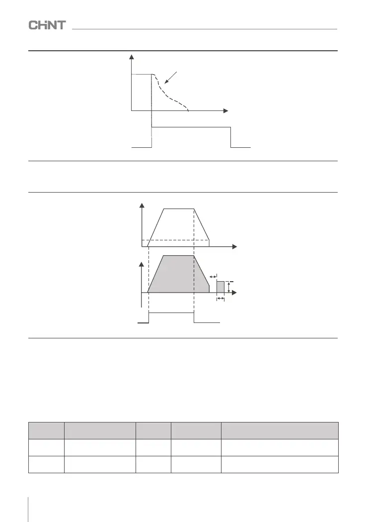
Frequency
Load speeds
Stop naturally by inertia
Time t
Stop command
● Deceleration to stop + DC braking
Set F1.05=2, the inverter decelerates to stop, and after the frequency drops to the starting frequency of
F1.06 DC braking at stop, the inverter starts DC braking.
Figure 8-3-6 Sequence diagram of deceleration stop + DC braking
Figure 8-3-5 Free stop timing diagram
Frequency
Hz
Output
Voltage
(effective)
Run command
Stop braking
starting
frequency
Time t
Stop braking
waiting time
DC
braking
quantity
Stop braking
time
048
NVF2G Series Inverter User's Guide
8.3.3 Acceleration and deceleration time and curve setting
Acceleration time refers to the time required for the inverter to accelerate from zero frequency to the
maximum output frequency of F0.07; deceleration time refers to the time required for the inverter to decelerate
from the maximum output frequency of F0.07 to zero frequency.
● Linear acceleration and deceleration
NVF2G provides 4 groups of acceleration and deceleration time, which can be switched and selected by
digital input terminal X. For example: select X5 and X6 as the input switching terminals, and form 2-digit binary
numbers in turn (where 1 means that the setting function of the X terminal is valid, and 0 means that the
setting function of the X terminal is invalid).
Function
code
Name
Set value
Predetermined
area
Parameter Description
F5.01
X5 terminal function
selection
28
0~63
28 : Acceleration and deceleration time
selection terminals
F5.02
X6 terminal function
selection
29 0~63
29 : Acceleration and deceleration time
selection terminal