052
NVF2G Series Inverter User's Guide
is limited by the torque limiter.
8.6.1 Vector speed control parameter setting
The slip compensation coefficient F3.07 is used to adjust the slip frequency of vector control and improve
the speed control accuracy of the system. Adjusting this parameter appropriately can compensate for the motor
speed deviation generated by asynchronous motors when the load increases, so that the motor speed can
remain basically stable when the load changes. The above parameters are only valid for vector control and are
not valid for V/F control. Below switching frequency 1 (F3.03), the PI parameters of the speed loop are: F3.01
and F3.02. At switching frequency 2 (F3.06) or above, the PI parameters of the speed loop are F3.04 and F3.05.
Between switching points, the PI parameter is obtained by linearly changing two sets of parameters. By
setting the proportional gain and integral gain of the speed regulator, the dynamic response characteristics of
vector control can be adjusted. Increasing the proportional gain and increasing the integration gain (reducing
the integration time) can both accelerate the dynamic response of the speed loop, but excessive proportional
gain or small integration time can easily lead to system oscillation and overshoot. A small proportional gain can
also easily lead to steady-state oscillations in the system, and there may be static velocity differences.
The PI parameters of the speed loop are closely related to the inertia of the motor system. Users need to
adjust them based on the default PI parameters for different load characteristics to meet the needs of various
occasions.
If vector control is used, motor parameter self-learning must be performed first, see 8.4 Motor parameter
self-learning.
0: SVC control
1: V/F control
Function
code
Name
Default
value
Predetermined area
Parameter Description
F0.00
Motor control method
1
0~1
F3.01
Speed Regulator Proportional Gain 1
30
1~100
-
F3.02
Speed regulator integral gain 1
0.5s
(0.01~10.00)s
-
F3.03
Switching frequency 1
5.00Hz
0Hz~F3.06
-
F3.04
Speed Regulator Proportional Gain 2
20
1~100
-
F3.05
Speed regulator integral gain 2
1.00s
(0.01~10.00)s
-
F3.06
Switching frequency 2
10.00Hz
F3.03~F0.07
-
F3.07
SVC slip compensation coefficient
100%
(50~ 200)%
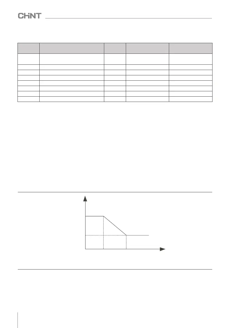
Figure 8-6-1 Schematic diagram of speed loop PI parameter switching
F3.01
F3.02
F3.04 F3.05
F3.04 F3.06
PI parameters
switching frequency 1 switching frequency 2
Frequency instruction
8.7 Overflow stall protection
During the operation of the inverter, if the current exceeds the overcurrent stall action current (factory
value 150% means 1.5 times the rated current of the motor), the overcurrent stall will take effect, and the output
frequency will begin to decrease until the current returns below the overcurrent stall point. After that, the
frequency starts to accelerate upwards to the target frequency, and the actual acceleration time is automatically
lengthened. The larger the overflow stall gain is, the stronger the overflow stall effect is, that is, the faster the
output frequency drops.