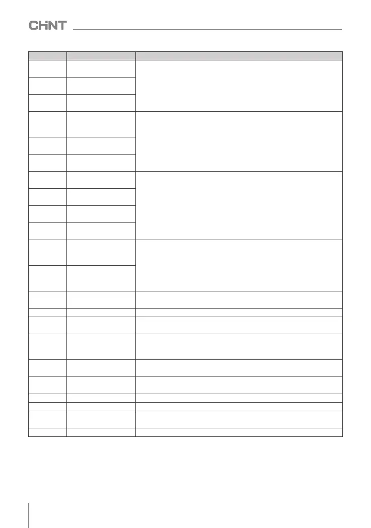
Set value
Function
Illustrate
15
command switch to
keyboard control
It is used to select different running signal sources, and can switch the inverter
running command among keyboard, terminal and communication
16
command switch to
terminal control
17
command to switch to
communication control
18
The main frequency
source is switched to
digital given
When this function terminal is valid, the main set frequency channel is forced
to switch to digital reference, AI1 or AI2
19
The main frequency
source is switched to AI1
20
The main frequency
source is switched to AI2
24
Multi-stage command
terminal 1
Through 16 states of these four terminals, 15 - stage speed setting can be
realized.
25
Multi-stage instruction
terminal 2
26
Multi-stage instruction
terminal 3
27
Multi-stage command
terminal 4
28
Acceleration and
deceleration time
selection terminal 1
Through the 4 states of the secondary terminal, the selection of 4 acceleration
and deceleration times is realized.
29
Acceleration and
deceleration time
selection terminal 2
34
Forward rotation
prohibited
Prohibit forward running
35
Reversal prohibited
Prohibition of reverse operation
36
Acceleration and
deceleration prohibited
Maintain current output frequency (except stop command)
37
UP/DN setting reset
When the main frequency is set through the panel, the terminal selects this
function to clear the frequency value changed by the up and down keys on
the keyboard, and restore the given frequency to the setting of F0.05
43
PID points suspended
PID is suspended, and the proportional adjustment and differential adjustment
are still valid at this time .
44
PID forbidden
PID function is invalid, if the frequency source is given by closed-loop PID ,
the system will switch to F9.29 channel setting
45
PID is reversed
PID is opposite to the direction set by F9.15
48
DC braking The inverter directly switches to the DC braking state
49
Frequency setting active
terminal
If the terminal is valid, it is allowed to modify the frequency, if the terminal is
invalid, it is forbidden to modify the frequency.
51
This run time is cleared
The time is reset to zero when the inverter is running this time
note: Serial numbers not listed in the table are "reserved".
8.11.2 Digital output terminal function (DO)
NVF2G series inverters are equipped with 1 multi-function digital output terminal and 2 multi-function
relay output terminals as standard, and each terminal can set the following output terminal functions.
058
NVF2G Series Inverter User's Guide