Page 10 of 40 IRIS Touch Engineering Manual Version 1.4
GPRS/3G SIM card (IRIS Touch 600NG or 640NG)
If you are using the GSM or GPRS connection then insert the GSM SIM card into the GSM SIM card holder.
Pin Inputs
The IRIS Touch dialler has 6 pin inputs that can be used to generate alarm messages. These can be:
Text messages via SMS (GPRS/3G).
SIA, Contact ID or Fast Format alarm messages over IP to the monitoring centre.
Note: These pin alarm inputs can also be used when the dialler is directly connected to an alarm panel via the
serial or RS485 connections.
Via Open/Close Contact Source
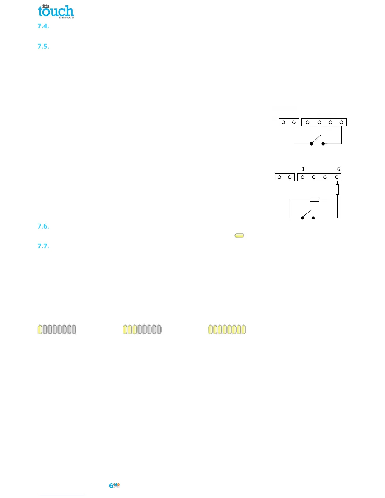
Each pin input is designed to be connected in a loop via an open/close contact
source from an alarm panel, or other device, to a reference ground pin available on
the IRIS dialler, as shown opposite.
Opening the contact (i.e. loop is open circuit) generates an alarm signal. Closing the
contact generates the equivalent restore signal.
Via Sense Resistors
It is also possible to link the contacts to the IRIS dialler via sense resistors so that
an open or short circuit tamper on the loop can be detected and the monitoring
centre alerted. In this case, the connections should be made as shown opposite.
Note: For this feature to work correctly it is essential that the resistors are
connected at the contact end of the loop and not the dialler end. The
monitoring centre must also enable the monitoring of this facility on the dialler
within the IRIS Secure Apps receiving system.
Switch On and Test
To confirm power is applied, look for the indicator SYS LED flashing yellow on the IRIS Touch dialler board.
GPRS/3G Network Scan (IRIS Touch 600NG or 640NG)
With the IRIS Touch 600NG or 640NG that are using the GPRS/3G communication you will need to perform a signal
strength check, to confirm that in the current installation you have the required signal strength for a reliable
connection.
GPRS/3G signal strength
Press and hold the “AP” button which will allow you to see the current signal strength indicated across the LEDs.
For a reliable GPRS/3G connection it is recommended that you have signal strength of 3 or more LEDs on as shown
on the examples below:
Signal strength too low Minimum signal strength Maximum signal strength
If the signal strength is below or close to minimum then try to reposition the antenna or use an external high gain
antenna to improve signal strength (if necessary) and rerun the signal strength test to gain best signal strength.
Once you have the required GPRS/3G signal strength you can then move onto the configuration.
 Loading...