MI00/10056 rev.1--05/2001-- page 35
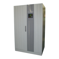
5.3 EDP70 PLUS 50/80kVA
Ensure the AC supplies and load are switched OFF. Check that all the EDP70 PLUS UPS Switches (behind the
front panel) are switched OFF, see figure 16.
The AC supply cables must be suitable for carrying the maximum supply demand. The voltage drop in the cable
should be minimized to ensure the AC supply voltage at the EDP70 PLUS UPS terminals is within +/- 10% of
nominal.
The EDP70 PLUS UPS should be connected to the main/reserve supplies and output load via a wall mounted
junction box.
Installation and connection should only be carried out by qualified electrical personnel.
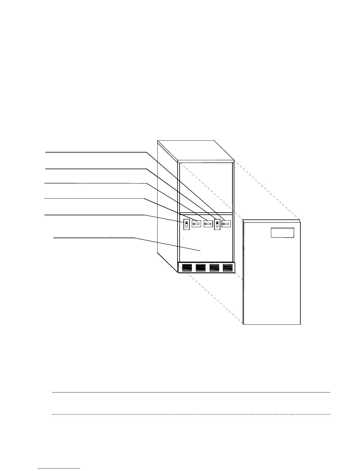
Figure 22 – 50/80kVA: Switches and Breakers
Terminal board compartment
S5 = RESERVE OUTPUT switch
S3 = BY-PASS switch
S2 = Equipment RESERVE switch
S4 = INVERTER OUTPUT Breaker
S1 = Equipment ON/OFF Breaker
 Loading...