Model 108 FLEX-AUGER® Feed Delivery System Installation
31
MA1714C
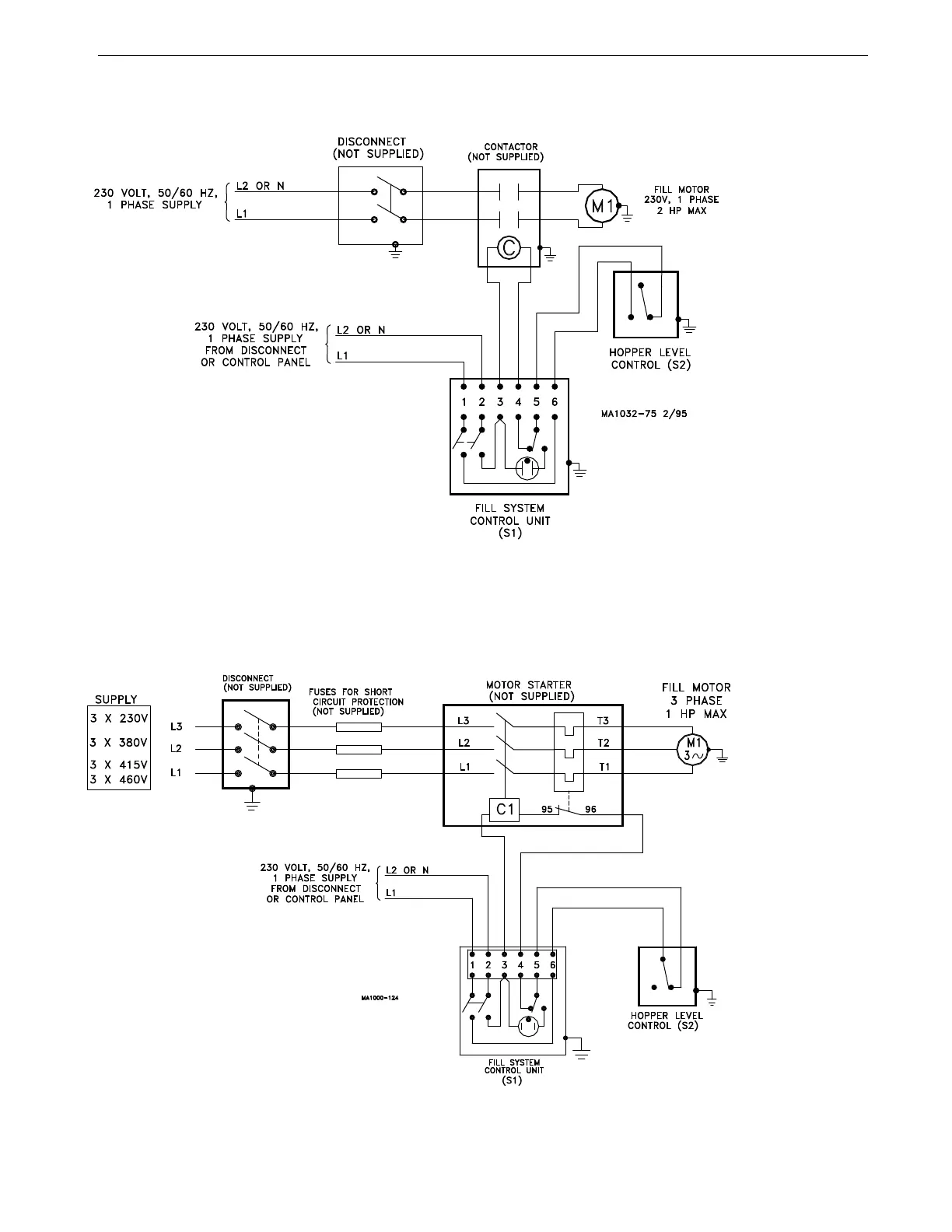
Wiring Diagram for Model 108 w/Hopper Control Switch
(1-1/2 H.P. or larger, 3 Phase)
Wiring Diagram for Model 108 w/Hopper Control Switch
Important: If a time clock is to be used
to control system, please refer to
applicable instruction.
Important: If system is to be con-
trolled by another style switch, please
refer to applicable instruction.
Figure 25.Model 108 Hopper Level Control Switch (1-1/2 HP or larger) Wiring Diagram
Important: If a time clock is to be used
to control system, please refer to
applicable instruction.
Important: If system is to be controlled by
another style switch, please refer to appli-
cable instruction.
Figure 26.Model 108 Hopper Level Control Switch Wiring Diagram