Installation Model 108 FLEX-AUGER® Feed Delivery System
30
MA1714C
Feed Level Control Installation
The Hopper Level Control (or Drop Tube Switch) is installed in the feed hopper (or on the drop tube over the
feeder) at the power unit end of the line. This switch stops the FLEX-AUGER
®
Feed Delivery System when
the last feeder is full. Install the hopper level control or drop tube switch according to instructions shipped
with the unit. Wire the switch into the system as specified in the appropriate wiring diagram in this manual.
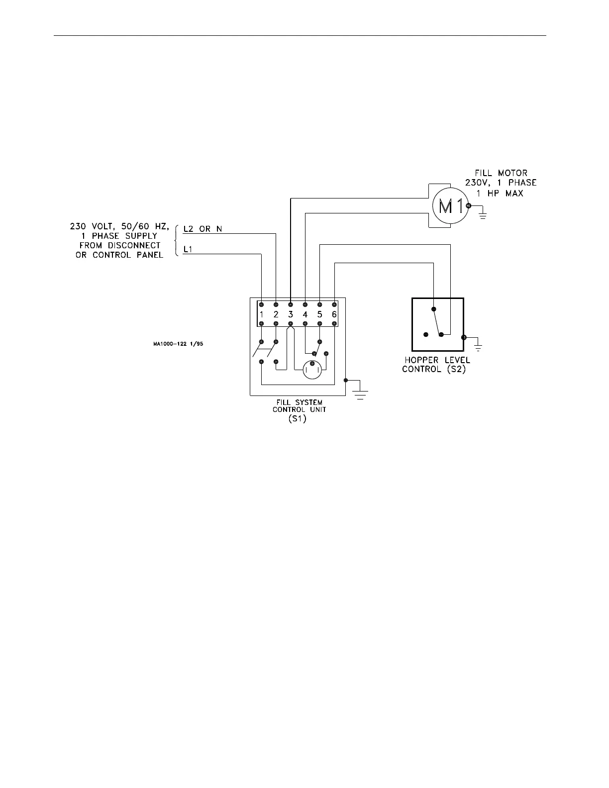
Wiring Diagram for Model 108 System w/Hopper Control Switch
(1 H.P. or smaller, Single Phase)
Important: If a time clock is to be used
to control system, please refer to
applicable instruction.
Important: If system is to be con-
trolled by another style switch, please
refer to applicable instruction.
Figure 24.Model 108 (1 H.P. or smaller) Hopper Level Control Switch Wiring Diagram
 Loading...

