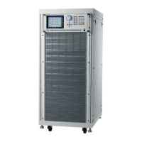
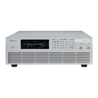
Programmable AC Source 61511/61512/61611/61612 Quick Start Guide
7
8
GPIB Connector
Remote controller uses GPIB bus to connect
the PC via the connector for remote operation.
9 Cable Connector
Select the mapping cable connector for
different input cable (Δ-Y). (Note: Not valid for
3-phase voltage input 480Vac (Y: L-L).)
10
Remote Sense
Connector
It is the terminal that senses the load directly
to avoid any voltage drop when connecting
cable. Ensure the “SL” terminal of remote
sense connector is connected to the “L”
terminal of Load, and the “SN” is connected to
the “N” of Load. Reverse polarity cannot be
connected.
11
Input Connecting
Terminal
It connects the mains to AC Source as input.
12
Output Connection
Terminal
It connects to UUT for output.
13
I/O Cable Secure
Strip
It secures the input/output connection cable.
Table 1-2 Rear Panel Description

 Loading...
