High Power DC Electronic Load 63200 Series Quick Start Guide
2.3 Application Connection
2.3.1 Load Connections
CAUTION
To satisfy safety requirements, load wires must be heavy
enough not to overheat while carrying the short-circuit
output current of the device connected to the Electronic
Load.
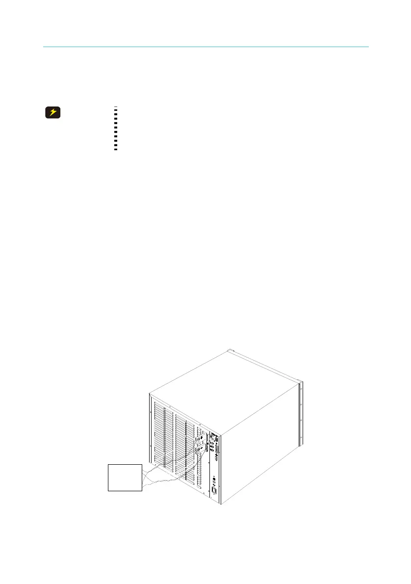
Input connections are made to the + and − terminal block on the rear of
the Load. The major considerations in making input connections are the
wire size, length and polarity. The minimum wire size required to avoid
overheating may not be enough to maintain good regulation. The wires
should be large enough to limit the voltage drop to less than 0.5V per lead.
The wires should be as short as possible, and bundled or tied together to
minimize inductance and noise. Connect the wire from the PLUS (+)
terminal to the HIGH potential output terminal of the power supply (UUT).
Connect the wire from the MINUS (−) terminal to the LOW potential output
terminal of the power supply (UUT). Figure 2-2 illustrates the typical
setup of the Load to the UUT. When using Model 63208, 63209, 63210
and 63211 the distance should be 1 meter for chassis front and 2.5
meters for rear without any foreign object blocking the vents or the
hardware temperature may rise and cause OTP.
+
_
UUT
Figure 2-2 Load & Remote Sensing Connection
8
 Loading...