23
Specifications
Input
Sensor Type 3-wire RTD, 100 W PT, 0.00385 W/W/˚C, 20 W balanced lead wire
Number of Sensor Inputs 1 or 2 per Circuit
Sensing Configuration Range: Single, Low, High, Average
Output
Power Switching SSR
Number of Circuits 1 or 2
Capacity 40 Amps per Circuit (Breaker size shall be 50 Amps maximum per
circuit or 125% of anticipated load)
Control Types
PID Control mode must be set to Auto
Autotune On or Off
Proportional Band, (˚F) Range: 1 – 100
Integral (sec/repeat) Range: 0 – 9,999
Rate or Derivative, (seconds) Range: 0 – 500
Manual Offset 0 - 1000 (0% - 100%)
On/Off Control mode must be set to Auto
Dead band, (˚F) Range: 2 – 100
Manual Range: 0 – 100%
Soft Start, Current Clamping Enable or Disable
Settings
Temperature (PV) Range: -80˚F to +1100˚F
Range: -62˚C to +593˚C
Low Temperature Alarm Range: -80˚F to +1050˚F, Off
Range: -62˚C to +566˚C, Off
High Temperature Alarm Range: -80˚F to +1150˚F, Off
Range: -62˚C to +621˚C, Off
Low Current Alarm Range: 0.1 A – 50.0 A, Off
High Current Alarm Range: 0.1 A – 50.0 A, Off
GFEP Range: 30mA – 150 mA, +/-2.5% of Span or +/- 3mA
GFEP Alarm Condition Alarm Only or Alarm & Trip
Output on Sensor Failure Mode Range: 0 – 100%, Bumpless Transfer to Manual Mode
Audible button depress Range: On, Off
Security 3 Levels of password protected security
Alarm State Normal Operation: Closed (default), Open
Display, HMI, Indication
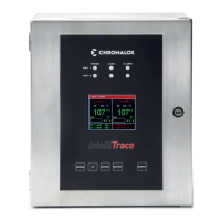
Display 3.5” 320 x 240 RGB Full color graphic TFT module
Human Interface 5 Capacitive Touch Input Buttons
LED Indication Power (Green), Load (Amber), Alarm (Red) – Per Ckt

 Loading...