28
Modbus Addendum
Modbus Serial Communications
The ITC supports Modbus serial communications. For
a complete description of the Modbus protocol refer to
the description provided at http://www.modicon.com/
or http://www.modbus.org/
Physical Layer
The Base address, bit rate and character format are
configured via menu interface.
Physical layer configuration settings possible are:
Data rate: 2400, 4800, 9600 (default), 19200,
38400, 56000 bps
Parity: None (default), Even, Odd
Character format: Always 8 bits per character.
The transmitter must not start transmission until 3
character times have elapsed since reception of the
last character in a message, and must release the
transmission line within 3 character times of the last
character in a message.
Note: Three character times = 1.5ms at 19200, 3ms at
9600, 6ms at 4800, 12ms at 2400
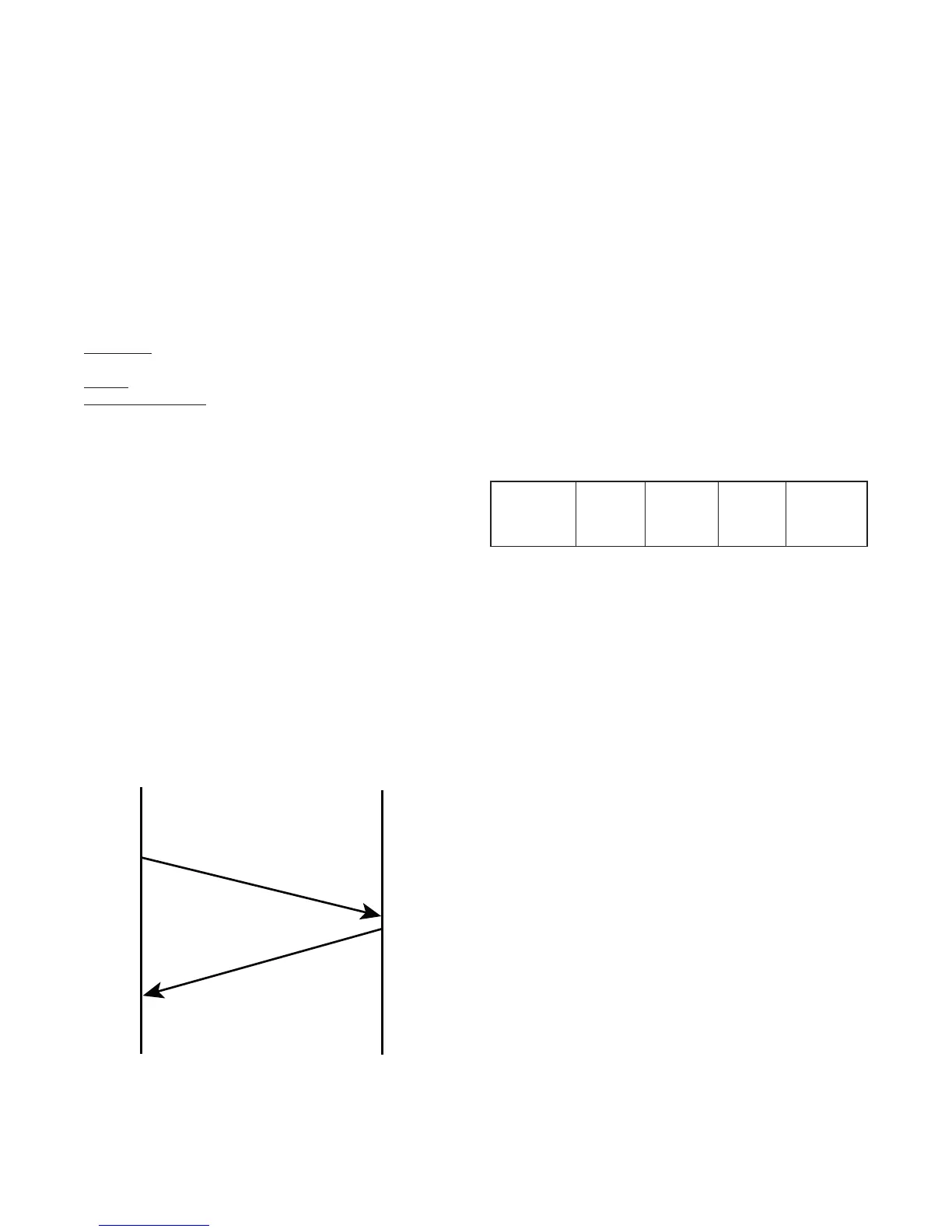
Link Layer
A Query (or command) is transmitted from the Modbus
Master to the Modbus Slave. The slave instrument as-
sembles the reply to the master. All of the instruments
covered by this manual are slave devices, and cannot
act as a Modbus Master.
MASTER
SLAVE
INSTRUMENT
QUERY
RESPONSE
Figure 1. Modbus Link Layer
A message for either a QUERY or RESPONSE is made
up of an inter-message gap followed by a sequence of
data characters. The inter-message gap is at least 3.5
data character times.
Data is encoded for each character as binary data,
transmitted LSB first.
For a QUERY the address field contains the address
of the slave destination. The slave address is given
together with the Function and Data fields by the Ap-
plication layer. The CRC is generated from the given
address, function and data characters.
For a RESPONSE the address field contains the ad-
dress of the responding slave. The Function and Data
fields are generated by the slave application. The CRC
is generated from the address, function and data char-
acters.
The standard MODBUS RTU CRC-16 calculation em-
ploying the polynomial 2
16
+2
15
+2
2
+1 is used.
Inter-
message
gap
Address
1 char.
Function
1 char.
Data n
char.
CRC
Check 2
char.
Device Addressing
The instrument is assigned a unique device address
by the user in the range 1 (default) to 255. To change
Modbus address, navigate to page 6 of the ITC Menu
page and select “MODBUS ID” parameter. Use Up and
Down keys to change the value. This address is used
to recognize Modbus Queries intended for this instru-
ment. The instrument does not respond to Modbus
Queries that do not match the address that has been
assigned to it.
The instrument will also accept global Queries using
device address 0 no matter what device address is
assigned. No responses are returned for globally ad-
dressed Queries.

 Loading...


