User Instructions
Note: All warnings and cautions denoted throughout this user’s manual also apply to the modifi cations listed below. Gen-
eral instructions and specifi cations referring to the open and closed loop systems apply to the fi eld-modifi ed units below.
Appendix B
microTHERM™: CMX Closed Loop to Open Loop Cooling Conversion
This sheet details the steps taken and material required to convert a Chromalox CMX microTHERM hot
water system from closed loop cooling to open loop cooling. The basic operation involves removing the
heat exchanger bundle and replacing it with a fl at plate. Please contact the Chromalox Customer Service
department for more information and to order the necessary materials.
New Material Required
1. 1/4” NPT Pipe Plug 1 piece Chromalox part number 218-075439-036
2. 1/4” NPT x 1-1/2” Nipple 1 piece Chromalox part number 198-122817-013
3. 1/4” NPT Elbow 1 piece Chromalox part number 107-122815-001
4. 1/4” NPT Close Nipple 1 piece Chromalox part number 198-122817-002
5. 1x1/2” NPT Reducer 1 piece Chromalox part number 032-120942-019
6. Open loop cooling fl ange 1 piece Chromalox part number 121-510702-017
Replacement Steps
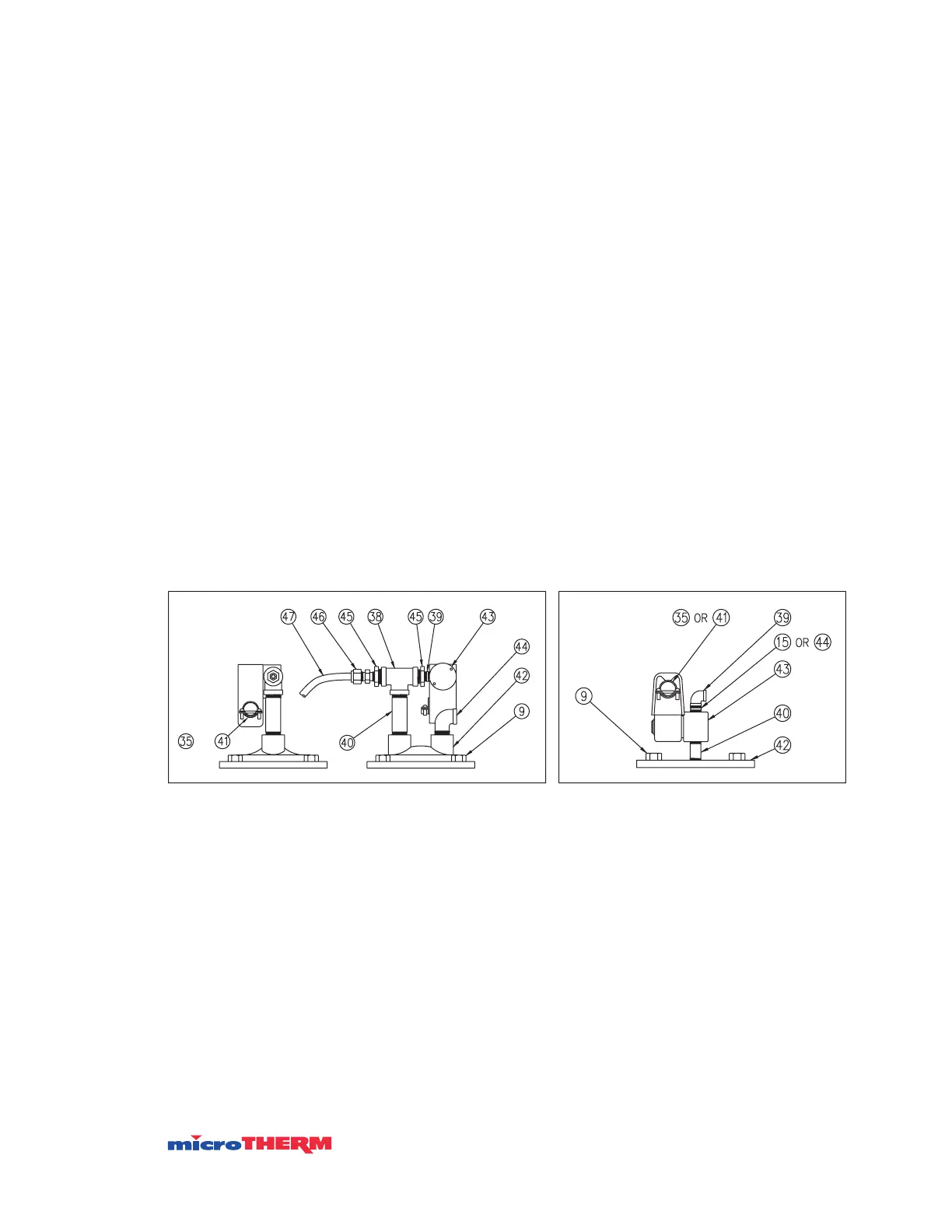
Figures 1 and 2 show the layout of the cooling confi guration for both closed and open loop cooling. These
parts are located on the top of the cooling chamber. Use pipe tape or other sealing compound when
attaching threaded connections.
Note: Refer to Figures 3 and 4 for location of components.
1. Remove (47) 3/8” copper tube and compression fi ttings from heat exchanger and tee above pump inlet.
2. Place 1/4” pipe plug into tee above pump inlet where copper tube was connected.
3. Pop magnetic coil from top of (43) solenoid valve and leave wired to system.
4. Remove (43) solenoid valve from top of heat exchanger and keep for reinstallation.
5. Remove four (9) bolts and lift (42) heat exchanger from cooling chamber.
6. Reuse rubber gasket and (9) bolts to attach new (42) cooling fl ange to cooling chamber.
7. Attach new (40) 1-1/2” nipple to fl ange.
8. Attach (43) solenoid and magnetic coil to nipple.
9. Attach new (15) close nipple and new (39) elbow to solenoid.
10. Replace 1” pipe plug from lower cooling chamber port with 1 x 1/2” reducer.
11. Lower cooling chamber port becomes the new cooling inlet.
Figure 1: Closed Loop Cooling Figure 2: Open Loop Cooling
or
43

 Loading...

