CIAS Elettronica S.r.l. Ed. 2.2
Installation Handbook page 33 to 43 ERMO 482
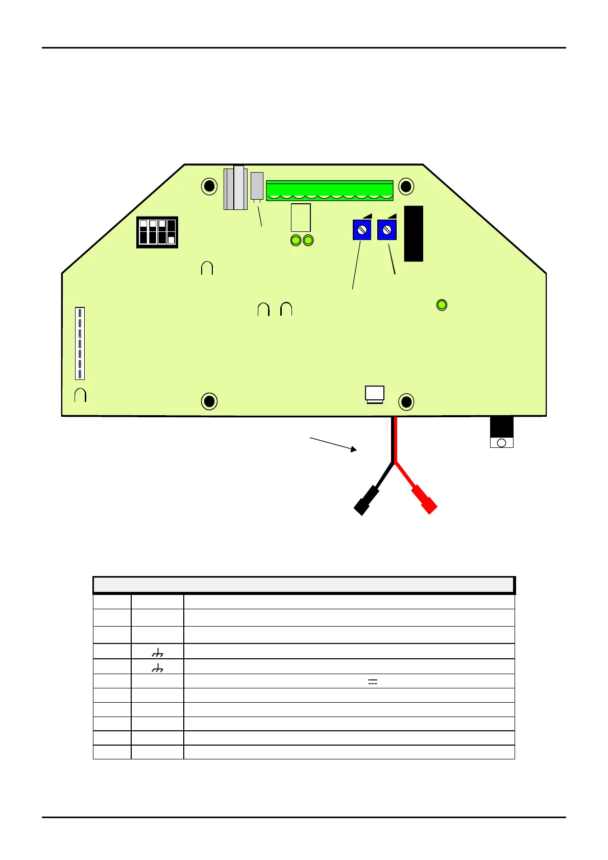
3.1.2 Receiver Circuit
The following figure and tables show the terminal block and connector function present on the
ERMO 482 RX board.
10
5
8
3
6
1
2
7
4
9
Tamper
Alarm
Led
Channel
Led
0.2 Vpp
5V
9V
Fuse
INT.
SEN.
Delay Adjustment
Sensitivity
Adjustment
Main
Led
1
1234
ON
OFF
Rag
2
3
4
5
6
7
RX
Red faston to battery positive
Channel
Selector
Test
Connector
Bulb
MW Connector
MS1
F1
DS1
Figure 9 Layout of connectors, jumpers, LED and presetting in receiver board
RECEIVER MS1 TERMINAL BLOCK
Mains ac Power Supply input (19 V~)
Mains ac Power Supply input (19 V~)
Power Supply positive input 13,8 V
Tamper relay contact (Normally Closed) + Bulb contact
Tamper relay contact ( Closed) + Bulb contact