© CIAS Elettronica S.r.l. Ed 1.6
Installation Manual Page 27 of 43 Sioux
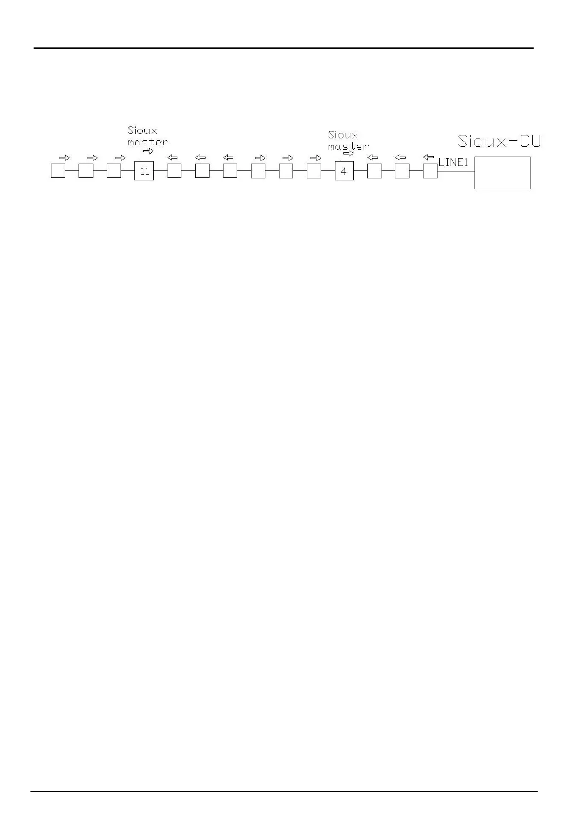
In the following diagram there is an example of the connections with the correct arrow
positioning.
The fixing of the screened containers inside the external boxes is by using two screws.
Ensure that before fixing the container inside the box the interconnection cables are inserted.
Insert the termination connector in the free connector of the last sensor, either in the left or right
branch.
2.3 Installation of the Sioux-CU
The Sioux-CU control unit is mounted in a special container which also houses the battery and
power supply.
To this will be connected the left and right sensor branches, the power, the container tamper and
possibly an RS485 serial cable for connection to an IB System R.
Switch ON the dip switches 1 and 2 of SETLINE1, SETLINE2, SETLINE3 to polarise the RS485
lines.
2.4 System configuration
Use the “Sioux test” software program to configure the system.
With this software it is possible to divide the global system into many sub-systems comprising
one Sioux-CU, 20 master and 120 slave in total 140 sensors.
Each sub-system can then be sub-divided into a maximum of 20 zones and each zone can be
assigned the required characteristics (intrusion alarm threshold, cut alarm threshold, etc.).
It is possible to assign the characteristics not only by zone but also by individual sensor. For a
more detailed description see the “Sioux test” manual.