© CIAS Elettronica S.r.l. Ed 1.6
Installation Manual Page 28 of 43 Sioux
3. CONNECTIONS
3.1 Circuit descriptions and functions
The following pages show the SIOUX components describing their various functions.
The system, in the maximum configuration, is designed for the protection of 700m of fence and is
made up of the following components:
• 1 Sioux-CU board + associated housing
• 20 Sioux Master boards + associated housings
• 120 Sioux Slave boards + associated housings
• 1 Battery charger power supply
• 1 Container for the Sioux-CU and the local power supply
• 1 Relay board (optional)
The connections between the sensors will be with pre-composed CIAS cables.
The connections to Sioux CU includes:
• 2 RS485 serial lines for connection of the sensors with associated power supplies
• 1 RS485 serial line for connection to the IB System R or to the relay board
• 1 Ethernet line for connection of the configuration software (Sioux Test) or the Server for
acquisition (polling) of the alarms (IB SYSTEM IP)
• 1 USB line for the connection of a configuration software (local)
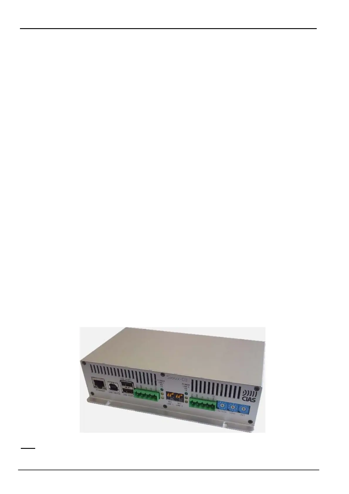
3.2 Sioux-CU
Sioux-CU performs the control unit function within the system.
It collects the electrical signals (in digital form) from the sensors, analyses them by means of
sophisticate Fuzzy Logic rules and, if alarm events are detected, sends them to external control
systems. In addition, Sioux-CU store all the events and associated signal values in an historical
and in a monitor file. It has an internal clock for date and time with a resolution of 1 second..
Sioux-CU can be powered from 13.8V by a suitable power supply or using an Ethernet network
with Power over Ethernet (PoE). (Option)
Sioux-CU comprises two boards:
- A core board with the microprocessor and the memory,
- An interface board containing all the peripherals: Ethernet, USB device and host, 3 RS485
serial lines, an expander with 4 balanced lines, an audio interface
N.B:
Connectors USB HOST, EXTERNAL BOARD CONNECTOR and AUDIO are actually not active.