© CIAS Elettronica S.r.l. Ed 1.6
Installation Manual Page 29 of 43 Sioux
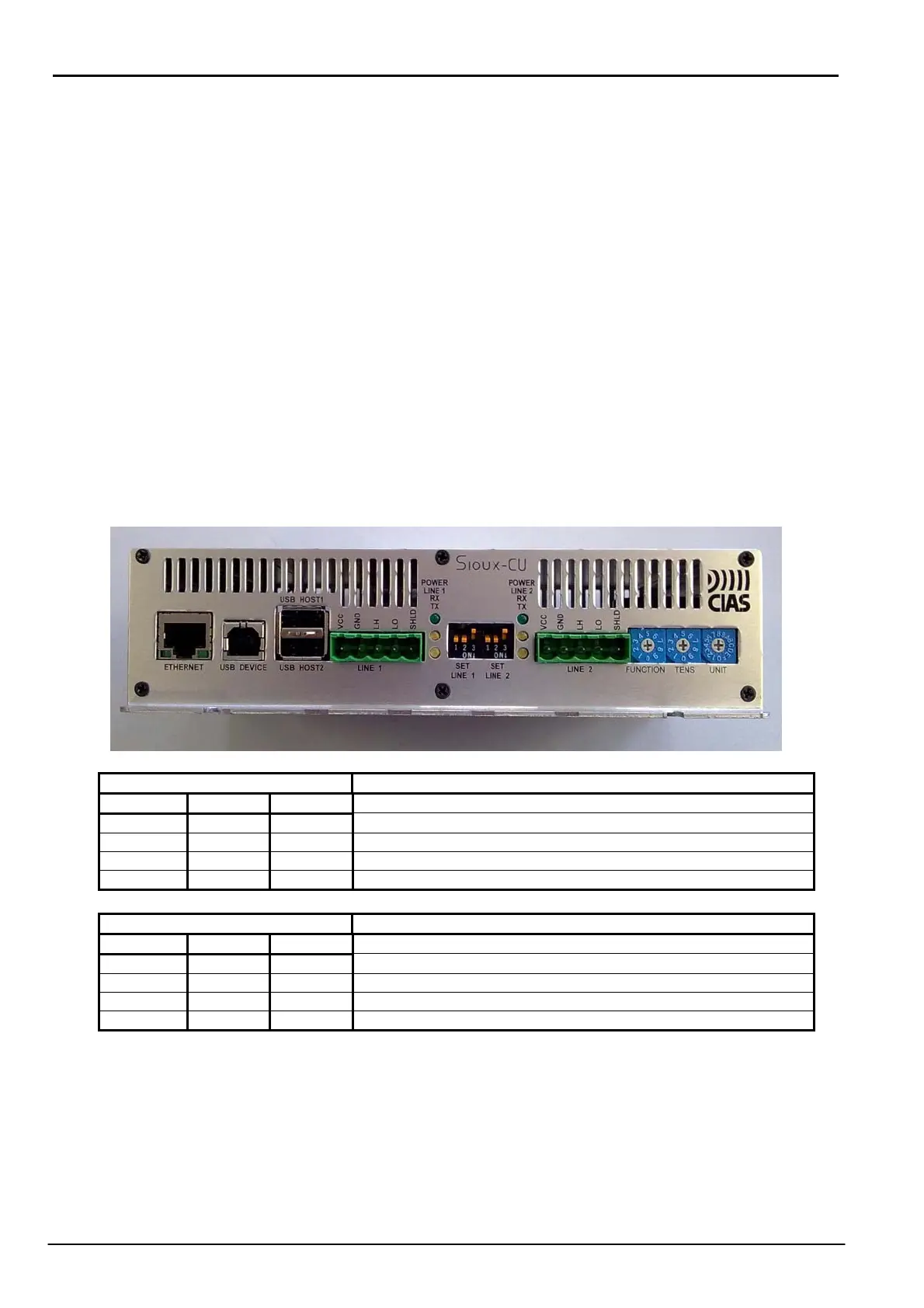
On the front plate, from the left are:
- 1 Ethernet connector with the possibility of power to the Sioux-CU via PoE (ETHERNET)
- 1 USB device connector (USB DEVICE)
- 1 connector with a double USB Host port (USB HOST1 and USB HOST2) not active.
- 1 RS485 serial line terminal block for connection of the left sensor line branch (LINE1)
- 3 led associated with the left branch: from the top a green led which indicates the
presence of power on the serial port terminals (POWER LINE1), a yellow led which
indicates the presence of received data (RX) and another yellow led which indicates the
presence of transmitted data (TX).
- 3 dip switch for setting the serial line: polarisation and termination (SET LINE1)
- 3 dip switch for setting the serial line: polarisation and termination (SET LINE2)
- 3 led associated with the right branch: from the top a green led which indicates the
presence of power on the serial port terminals (POWER LINE2), a yellow led which
indicates the presence of received data (RX) and another yellow led which indicates the
presence of transmitted data (TX).
- 1 RS485 serial line terminal block for connection of the right sensor line branch (LINE2)
- 1 hexadecimal switch for function selection (FUNCTION)
- 2 decimal switches for selection of a number between 0 and 99 (TENS and UNITS)
SET LINE1 LINE1 Termination settings
DIP1 DIP2 DIP3
OFF OFF OFF Line not terminated and not polarised
ON ON OFF Line polarised and not terminated
OFF OFF ON Line terminated and not polarised
ON ON ON Line terminated and polarised
SET LINE2 LINE2 Termination settings
DIP1 DIP2 DIP3
OFF OFF OFF Line not terminated and not polarised
ON ON OFF Line polarised and not terminated
OFF OFF ON Line terminated and not polarised
ON ON ON Line terminated and polarised
For optimum operation of the serial lines LINE1, LINE2 and LINE 3 is recommended to set them
into polarized and not terminated mode