© CIAS Elettronica S.r.l. Ed 1.6
Installation Manual Page 30 of 43 Sioux
LINE1 Description
VCC Power supply output:13.8 V
GND Ground
LH RS485 High Line
LO RS485 Low Line
SHLD Shield
LINE2 Description
VCC Power supply output:13.8 V
GND Ground
LH RS485 High Line
LO RS485 Low Line
SHLD Shield
LED Function Description
POWER LINE1 Indicates the presence of power on VCC of LINE1
RX Indicates message reception
TX Indicates message transmission
LED Function Description
POWER LINE2 Indicates the presence of power on VCC of LINE2
RX Indicates message reception
TX Indicates message transmission
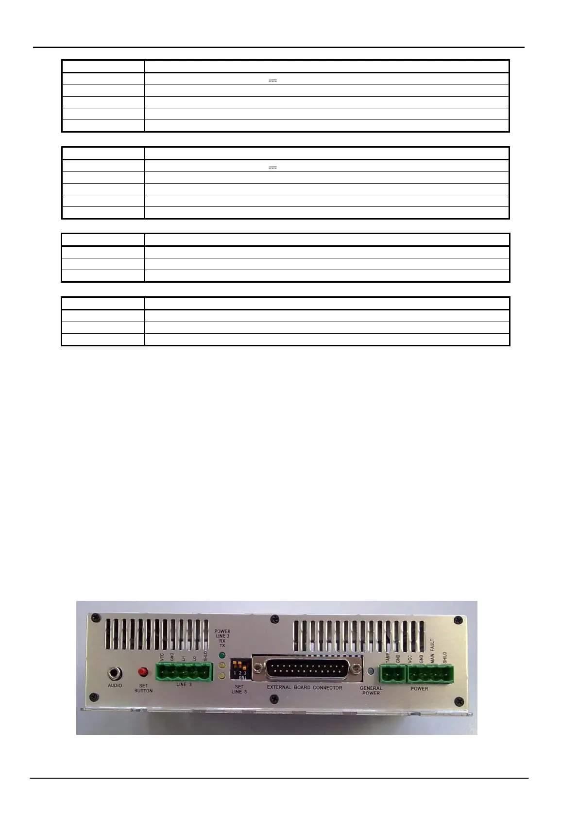
On the rear plate, from the left are:
- 1 Audio Jack (AUDIO) actually not active.
- 1 Push button (SET BUTTON)
- 1 RS485 serial terminal block for the connection of the Sioux-CU to the IB-System or to
the relay cards (LINE3)
- 3 led associated with serial LINE3: from the top a green led which indicates the presence
of power on the serial port terminals (POWER LINE3), a yellow led which indicates the
presence of received data (RX) and another yellow led which indicates the presence of
transmitted data (TX).
- 3 dip switch for setting the serial line: polarisation and termination (SET LINE3)
- 1 connector for connection a 4 x balanced line expansion board
(EXTERNAL BOARD CONNECTOR) actually not active.
- 1 green led which indicates the presence of power (GENERAL POWER)
- 1 two way terminal block for connection of a tamper contact
- 1 four way terminal block for power and power presence (POWER)