© CIAS Elettronica S.r.l. Ed 1.6
Installation Manual Page 31 of 43 Sioux
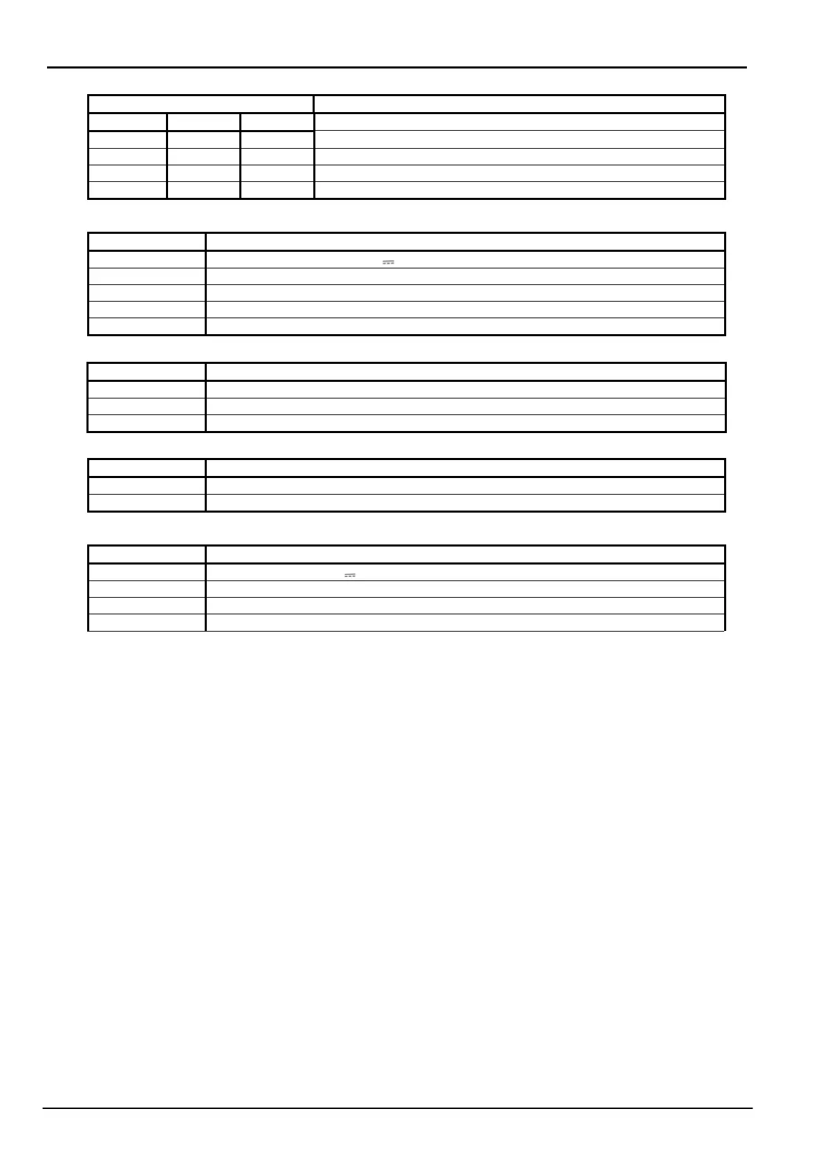
SET LINE3 LINE3 Termination settings
DIP1 DIP2 DIP3
OFF OFF OFF Line not terminated and not polarised
ON ON OFF Line polarised and not terminated
OFF OFF ON Line terminated and not polarised
ON ON ON Line terminated and polarised
LINE3 Description
VCC Power supply output:13.8 V
GND Ground
LH RS485 High Line
LO RS485 Low Line
SHLD Shield
LED Function Description
POWER LINE3 Indicates the presence of power on VCC of LINE3
RX Indicates message reception
TX Indicates message transmission
TAMPER Description
TAMP Tamper input
GND Ground
POWER Description
VCC Power supply: 13.8 V
GND Ground
MAIN FAULT Power present
SHLD Shield
NB: If you use only the controller, the connection between the unit and the power supply must be
realized with cable of correct section (it must be greater than 1,5mm²). The cable must be
shielded type, with shield connected to ground.
3.2.1 Function Descriptions
By adjusting the hexadecimal switch it is possible to select one of the following functions
- 0: normal polling of sensors on two serial lines LINE1 and LINE2
- 1: automatic assignment of the device numbers of the Sioux-master boards
- 2: allocation of the number of the Sioux-CU
- 3: manual assignment of the Sioux-master device numbers present on the left branch
- 4: manual assignment of the Sioux-master device numbers present on the right branch
- 5: zone configuration with “touch and zone” procedure
- 6: change of the left branch sensor number
- 7: change of the right branch sensor number
-8: Store Cut Prealarm Events
Once the hexadecimal switch is positioned on the desired function, push the SET BUTTON to
activate the function.