© CIAS Elettronica S.r.l. Ed 1.6
Installation Manual Page 40 of 43 Sioux
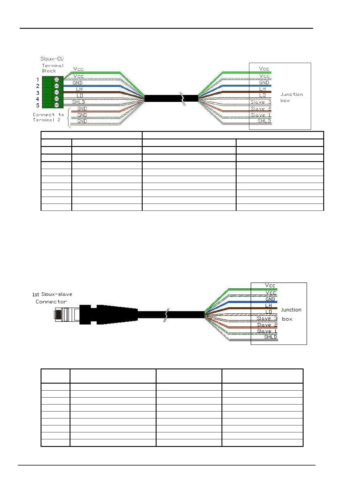
With this solution the following cable is required:
- Cable between Sioux-CU and distribution box
Sioux CU line 1 or line 2 Junction Box
Terminal Terminal function Wires Colour Junction Box Functions
1 Power supply 13.8 V Green Power supply 13.8 V
1 Power supply 13.8 V White/Blue Power supply 13.8 V
2 GND White/Orange GND
2 GND Orange GND
2 GND White/Green GND
2 GND Blue GND
3 RS485- High Line LH Brown RS485-Linea alta LH
4 RS485- Low Line LO White/Brown RS485-Linea bassa LO
5 Shield Shield Shield
REMARKS:
- Connect White/Orange, Orange, White/Green, and Blue wires together to terminal 2
(GND) of the Sioux CU terminal block.
- Connect Green and White/Blue wires together to terminal 1 (Vcc) of the Sioux CU
terminal block.
- Cable between junction box and first Sioux-slave
REMARK Using only precabled cable, check that colors correspond to numbering of
RJ45 connector’s pin.
Pin
RJ45
1
s
slave Connector
Functions
Wires Colour Functions Junction box
1 GND White/Orange GND
2 GND Orange GND
3 GND White/Green GND
4 GND Blue GND
5 Power supply 13.8 Vcc White/Blue Power supply 13.8 Vcc
6 Power supply 13.8 Vcc Green Power supply 13.8 Vcc
7 RS485- Low Line LO White/Brown RS485- Low Line LO
8 RS485- High Line LH Brown RS485- High Line LH
Shell Shield Shield Shield