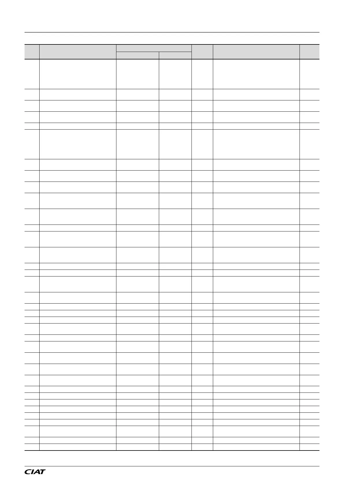
No, Description
Setting
Unit Display conditions
Access
level
Enumeration By default
171 Temperature setpoint 2 in cooling mode 30,0 °C
P160 Setpoint 1/setpoint 2 selection = sched./
CMS, or On/Off input only or forcing
and
P161 Application of the setpoint 1/setpoint 2
selection = temperature or temperature +
ventilation
1
172
Temperature control PID proportional band
(P) in cooling mode
5,0 °C 2
173
Temperature control PID integral time (I) in
cooling mode
600 s 2
174
Temperature control PID derivative time (D)
in cooling mode
0 s 2
180 Temperature setpoint 1 in heating mode 23,0 °C 1
181 Temperature setpoint 2 in heating mode 18,0 °C
P160 Setpoint 1/setpoint 2 selection = sched./
CMS, or On/Off input only or forcing
and
P161 Application of the setpoint 1/setpoint 2
selection = temperature or temperature +
ventilation
1
182
Temperature control PID proportional band
(P) in heating mode
5,0 °C 2
183
Temperature control PID integral time (I) in
heating mode
600 s 2
184
Temperature control PID derivative time (D)
in heating mode
0 s 2
206
Free cooling and night cooling operating
differential compared to the controlled
temperature
3,0 °C
P150 Free cooling control = With
or
P151 Night cooling control = With
2
207
Temperature low limit for free cooling and
night cooling
15,0 °C
P150 Free cooling control = With
or
P151 Night cooling control = With
2
210 Control setpoint in night cooling mode 17,0 °C P151 Night cooling control = With 1
212
Air intake fan ow rate setpoint in night
cooling mode
10000 m
3
/h
P151 Night cooling control = With
and
P104 Air intake ventilation control = Flow rate
2
213
Air extraction fan ow rate setpoint in night
cooling mode
10000 m
3
/h
P151 Night cooling control = With
and
P104 Air intake ventilation control = Flow rate
2
216 Air quality setpoint 800 ppm P152 Air quality control = With 2
217 Air quality proportional band 100 ppm P152 Air quality control = With 2
218 Air ow max setpoint on intake for air quality 10000 m
3
/h
P152 Air quality control = With
and
P104 Air intake ventilation control = Flow rate
2
225
Temperature difference for recovery unit run
authorisation
3 °C 2
228 Frost protection temperature setpoint 17,0 °C P154 Target temperature selection = room 2
230 Supply air temperature low limit setpoint 16,0 °C 156 Supply air limitation = with 2
231 Supply air temperature upper limit setpoint 26,0 °C 156 Supply air limitation = with 2
232
Supply air temperature limit proportional
band
20,0 °C 156 Supply air limitation = with 2
233 Supply air temperature limit (I) integral time 150 s 156 Supply air limitation = with 2
234
Low supply air temperature compensation
setpoint in deadband
16,0 °C P157 Supply air compensation in deadband 2
235
Low supply air temperature compensation
proportional band in deadband
5,0 °C P157 Supply air compensation in deadband 2
236
High supply air temperature compensation
setpoint in deadband
35,0 °C P157 Supply air compensation in deadband 2
237
High supply air temperature compensation
proportional band in deadband
5,0 °C P157 Supply air compensation in deadband 2
240 Supply air temperature low limit threshold 15,0 °C 2
241 Supply air temperature upper limit threshold 45,0 °C 2
242 Return air temperature low limit threshold 15,0 °C P154 Target temperature selection = return air 2
243 Return air temperature upper limit threshold 35,0 °C P154 Target temperature selection = return air 2
244 Room temperature low limit threshold 15,0 °C P154 Target temperature selection = room 2
245 Room temperature upper limit threshold 35,0 °C P154 Target temperature selection = room 2
248
Hydraulic coil frost protection safety
threshold
4,0 °C
P28 Hydraulic coil no.1 = Cooling or Heating or
mixed
3
260 Coil valve min. opening percentage 0 % P28 Hydraulic coil no.1 = Cooling or Heating or mixed 2
265 Fresh air temperature limit for unit operation -20 °C 3
9 - PARAMETERS
EN-53 FLOWAY ACCESS