EN - 18
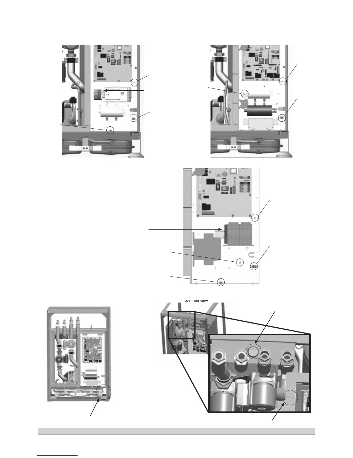
groove used for transmitting control
signals (sensors, thermostats, etc.)
Front view
3/4 front view
Detail with top view
Power cable routing next to the expansion
vessels (right-hand side)
Power supply to the heat pump and/or power supply to the 4
kW
GeoCIAT
TM
Modular
electric heating element optional kit
Power cable routing
Control cable routing
use of a grommet for the
options (e.g. Geocooling
option kit or control of
BALLON ECS 170L
three-way valve)
WARNING: the power cables MUST follow this route.
To be added as
an option
(e.g. 4kW GeoCIAT
TM
Modular
heating element kit)
33H and 45H models 33H and 45H models with integrated starter
Customer supply cable clamp (1) and Omega fastener (2)
For the electric heating element kit (option) use the cable clamp (3)
Customer supply cable clamp (1) and Omega fastener (2)
For the electric heating element kit (option) use the cable clamp (3)
45HT models
Customer supply cable clamp (1) and
omega fastener (2)
For the electric heating element kit
(option), use the cable clamp (3) and
the Omega fastener (4)
To be added as an option
(e.g. 4kW GeoCIAT
TM
Modular
heating element kit)
 Loading...