NA 12.54 D EN - 10
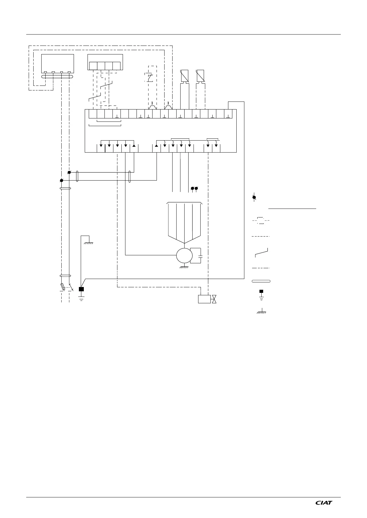
9 - WIRING SCHEMATIC DIAGRAM FOR INDIVIDUAL UNITS
C NC P N
20 21 22 23
A
D
PR
KF
BS
BSA
5V
20
A
21
B
22
23
24 25
26
27
28
29 30
31 32
33
34
35
36
37
A B D1 D2 S1 S2
0-10V
N
L
10A
3A 0,1A
06 07 08 09 10 11 1201 02 03 04 05
POWER IN
230 V
V300
TERMINAL
MASTER SLAVE
1
2
1
2
Q
L
N
N
Y
MK
V1
V2
V3
V4
V5
Cd
PV
MV
GV
A
BS
BSA
D
KF
MK
PR
Q
X
Y
User terminal
Return temperature sensor
Changeover sensor
Controller
Window switch
Air handling fan
Pump unit
Fused isolator
Shunt (remove if
equipment connected)
Solenoid valve
Connection terminal
Green/Yellow
Shared
Green/Yellow
Brown
Blue
Brown
Blue
Blue
Brown
Blue
Ivory
Blue
Brown
Green
Blue
Yellow
Grey
Black
Green/Yellow
Brown
Grey
Black
Speed selection as per ARC
Equipment to be provided by
the customer CIAT assembly
optional
Customer connection
Shielded twisted pair
Customer connection
if component supplied
separately
Multi-conductor cable
Earth terminal
Earth
Controller/Terminal connection: shielded twisted cable: see p20
Shielding to be connected to terminal 23 on the controller and terminal end
Certain problems may be resolved by checking some fundamental points. Check using the list below before requesting servicing.
Warning: When the controller is switched on, control will only take effect after a few minutes of system initialisation. (the terminal
segments come on approximately every 2 seconds)
Upon a mains power cut:
1. When the power returns, the controller restarts in Comfort mode in all cases:
→ However, it does not store:
- The setpoint override (returns to the midpoint)
- The ventilation speed (returns to Auto)
2. Error message: diagnostic d07 gives the controller's Alarm state.