NA 12.54 D EN - 20
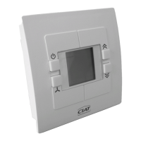
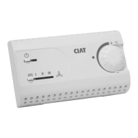
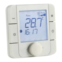
Wall-mounted installation
Warning!
This unit must be installed in accordance with the connection diagram inside the housing. It must be installed in accordance
with accepted engineering standards and must conform with current local standards. In order to meet Class II requirements, the
corresponding installation instructions must be observed.
Mounting: on flush-mount box using the holes provided. Cables routed via the opening in the mounting plate.
Wiring:
- Remove the terminal's front panel
- Connect as per the unit diagram (see p 10)
Power supply
- 230/1/50 Hz or 230/1/60 Hz
Terminal/Controller connection
- Max. distance between the room terminal/Controller: 30 m.
→ Including the cable length required for the first slave, if applicable
- RS485 type wiring: 4 wires + shielding: 2 twisted pairs with shielding connected to the comfort unit earth (mandatory), see
"Master/Slave connection" characteristics
→ Pair 1: A+ and B-, polarity to be observed
→ Pair 2: 5V and
┴
→ Shielding
┴
controller and terminal end
Master/Slaves connection
- 15 slaves max.
- Max. distance between the master and the 1st slave: 30m including cable length for room terminal
- Max. distance between 2 Slave controllers: 30 m
- Wiring:
→ RS485 type + 2 wires + shielding
→ Topology: controllers wired in series
→ Polarity to be observed
→ Flexible cable with 1 or 2 shielded twisted pairs with shielding continuity and shielding connected to the Master
comfort unit earth
→ Pair 1: A+ and B-, polarity to be observed
→ Pair 2:
┴
(if existing)
→ Shielding
┴
continuity between the Master and Slave controllers
→ Max. capacity between cables: 150 Cc/m
→ Filotex FMA-2P type cable, Belden ref. 9842/9842NH 24AWG or equivalent 2 shielded twisted pairs
Window contact input
- Wiring: 2 x 1 mm2 shielded twisted with shielding connected to the comfort unit earth.
- To be cabled to the Master and/or individual units only
We recommend marking the cables between the Master/Slave and Slave/Slave (from-to) in preparation for maintenance or site
developments over time.
Site monitoring and maintenance:
For the purposes of site monitoring and maintenance over time, we recommend that you have the following information:
An installation plan for equipment in the building, with a bus diagram
(Master/Slave and Zone clock bus if included)
Marking of the Master devices and their slave per unit
The position of the room thermostats and the device connected to them.
A summary of the types of bus cables used and their length
The position of the zone clock in the building (if included)
Note: when using the CIAT after-sales service, all of the above information will be requested by CIAT Services technicians before
any work.
Entered contact of window
- Cabling: 2 x 1 mm2 twisted armored with connecting of the armor plating on the earth(ground) of the unity(unit) of comfort.
- To cable on the units Masters(Teachers) and/or individual only
19 - ELECTRICAL CONNECTIONS - CABLE TYPES