EN
EN - 15 N 12.54 D
. It is possible to diagnose units still being controlled by the terminal and find out via the d00 how many slaves are still connected
by pressing the key.
. The limit for a master/slave loop is 15 slaves max. per master (see schematic diagram with maximum cable length between
master and slave)
. If a slave still has a room terminal, check that P09 = 2 imperative.
It will display the state of this Slave controller + the T° measured by the Master (if room sensor priority) or the T° measured by its
own sensor (if return sensor priority), as the keypad keys are inactive (parameters and diagnostics for this slave are accessible
for diagnostic purposes)
Inputs D1 & D2:
. If Input configured with "Alarm" (condensate pump, motor fault, etc.):
→ If alarm on the master:
The master is powered off and displays and ; the keypad keys are locked.
The slaves on the loop continue to operate in the last state indicated by the Master.
The slaves remain controlled by the V300 Zone timer, if included.
→ If there is an alarm on one of the slaves:
Only the slave concerned is powered off, the other units continue to operate as per the orders from the Master and its room
terminal.
. If the Input is configured to one of the 4 operating modes:
→ If triggered on the master:
The entire Master/Slave loop switches to the mode defined by the input configuration.
Only a lower mode may be set using the wall-mounted terminal (depending on the sleep button configuration)
For window switches: (Frost protection mode):
They must all be connected in series to the Master
→ If triggered on one of the slaves:
Only the slave concerned switches to the mode defined by the input configuration.
Setting the parameters on a Master/Slave loop:
Modifying a parameter on the Master unit will also modify the Slave unit
→ See Parameters table including the list of parameters sent from the Master to its Slaves (pp 7 & 8)
→ Warning: Modifying one parameter directly on a slave in the loop will modify the same parameter on all the slaves
located below it. To modify only the slave concerned, disconnect the bus (via the quick connector) and connect a terminal to carry
out the operation.
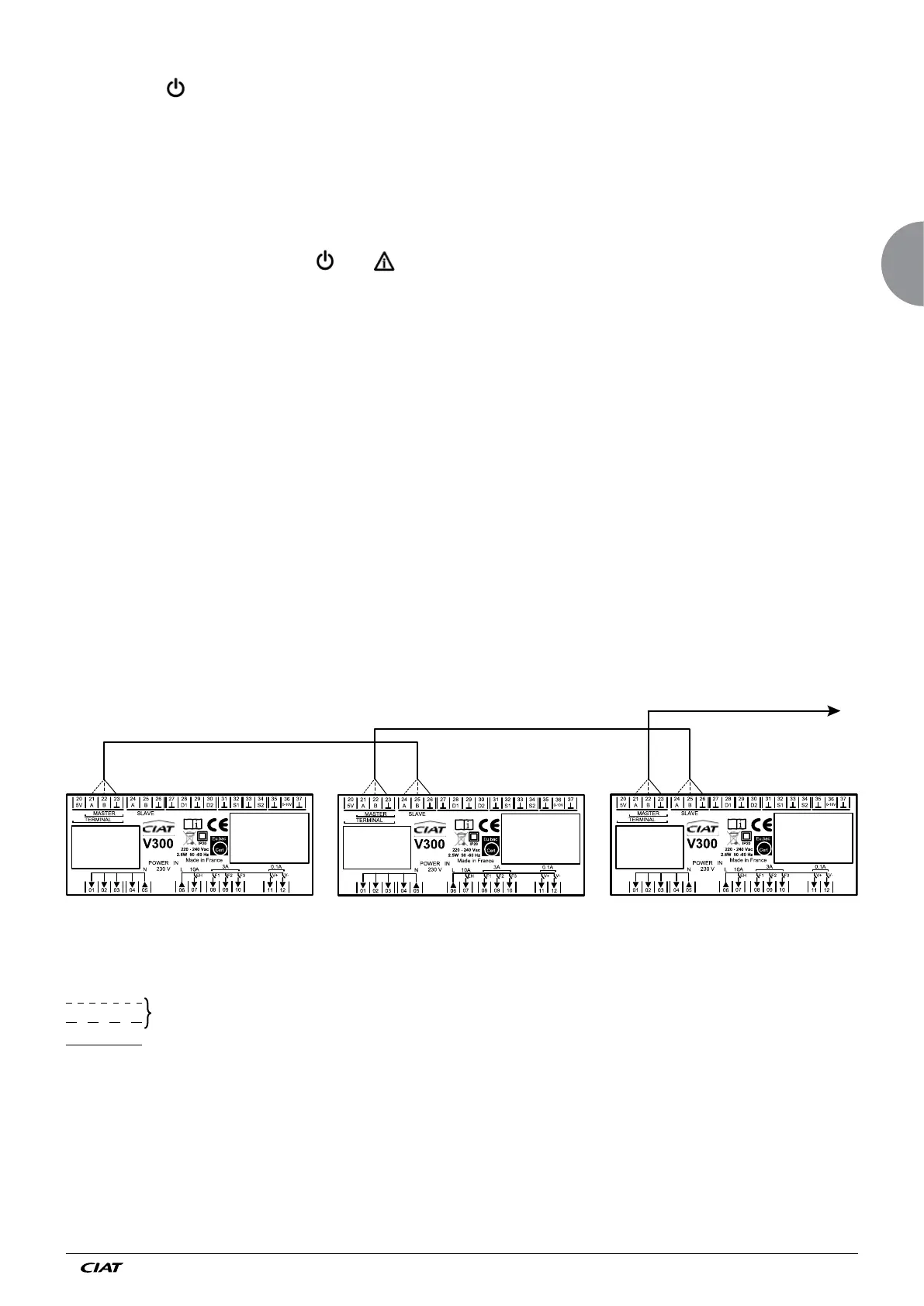
Connection diagram: Master/Slave
(1)
(2)(2)(2)(2)
V300 Master V300 Slave 1 V300 Master 2
Shielding
1 x Twisted pair
(1) To Slave N: terminals 24, 25 - 30 metres maximum
Mark the buses in preparation for maintenance or site developments.
(2) Shielding: mandatory continuity/terminal = 23.
See diagram 7415354