2-1
3930 Service Delivery Switch Hardware Installation and Start-up Manual
009-3223-001 Standard Revision E
Copyright
©
2012-2014 Ciena
®
Corporation January 2014
Installation 2-
The 3930 is designed for deployment in Outdoor Street Cabinets, huts and
other unconditioned locations. The 3930 can also be deployed in a central
office environment. The 3930 Service Delivery Switch can be mounted in a
standard equipment rack and requires 1 RU of space.
This chapter provides installation instructions. It discusses the following
topics:
• “Package Contents”
• “Important Safety Information”
• “Mounting the Device”
• “Grounding”
• “Power Supply Modules”
• “Transceivers”
• “Cable Installation and Guidelines”
• “Initial Configuration”
Package Contents
Upon receipt, examine all shipping containers and their contents. Carefully
unpack the 3930 from the packing material. Visually inspect all parts for
damage.
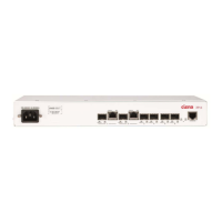
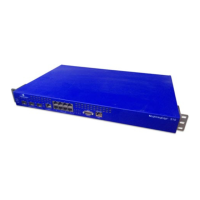
The following items are shipped with the 3930:
• Chassis (with the power supply slot PSA empty)
• Filler plate (installed over the slot PSB)
• Grounding screws (the 2 grounding screws will be attached to the back of
the chassis in the center, see Figure 2-1 on page 2-5)
• Mounting bracket kit for 19” frame (two brackets, four cable supports, four
8-32 x 1/2 length screws used to attach the cable supports to the brackets,
and eight 8-32 x 5/16 length pan head screws used to attach the brackets
to the side of the chassis. See Figure 8-2 on page 8-4.)


 To Next Page