D-3
Cisco 3900 Series, Cisco 2900 Series, and Cisco 1900 Series Integrated Services Routers Generation 2 Software Configuration Guide
Appendix D Changing the Configuration Register Settings
About the Configuration Register
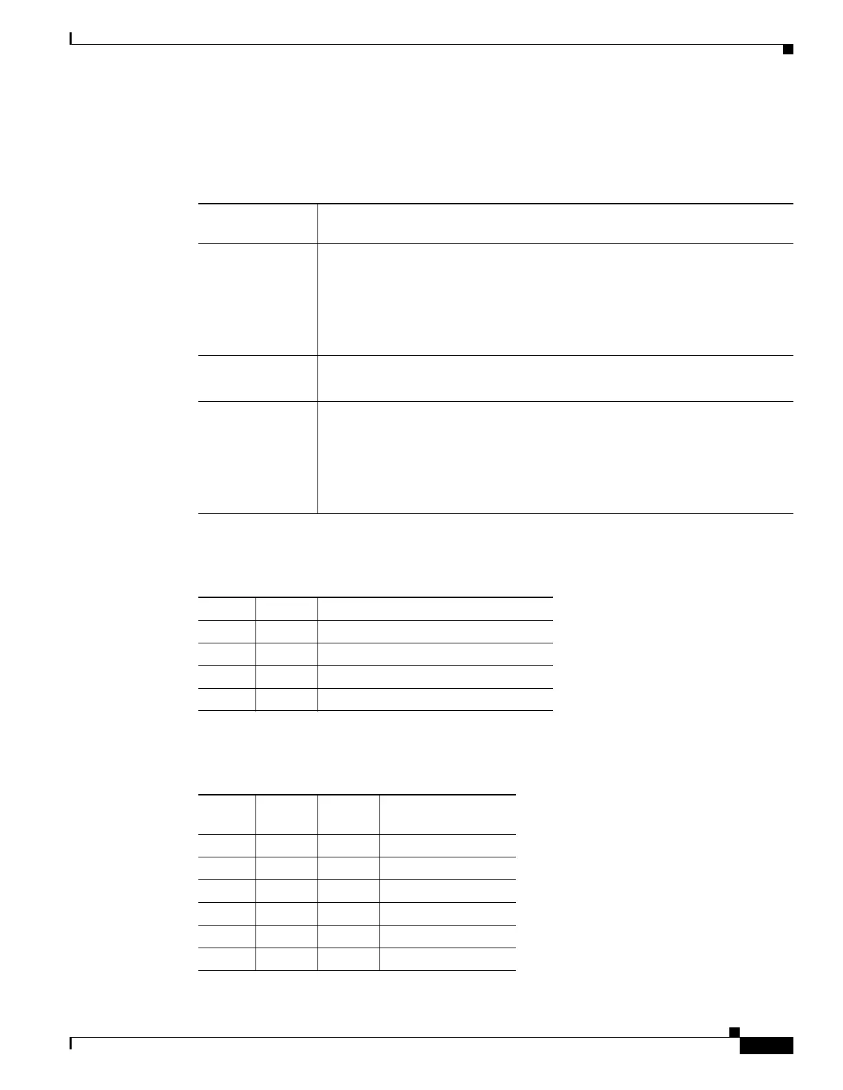
Table D-2 describes the boot field, which is the lowest four bits of the configuration register (bits 3, 2,
1, and 0). The boot field setting determines whether the router loads an operating system and where the
router obtains the system image.
Table D-3 shows how each setting combination of bits 10 and 14 affects the IP broadcast address.
Table D-4 shows the console line speed for each setting combination of bits 5, 11, and 12.
Table D-2 Boot Field Configuration Register Bit Descriptions
Boot Field
(Bits 3, 2, 1, and 0) Meaning
0000
(0x0)
At the next power cycle or reload, the router boots to the ROM monitor (bootstrap
program). To use the ROM monitor, you must use a terminal or PC that is
connected to the router console port. For information about connecting the router
to a PC or terminal, see the hardware installation guide for your router.
In ROM monitor mode, you must manually boot the system image or any other
image by using the boot ROM monitor command.
0001
(0x01)
Boots the first image in flash memory as a system image.
0010 - 1111
(0x02 - 0xF)
At the next power cycle or reload, the router sequentially processes each boot
system command in global configuration mode that is stored in the configuration
file until the system boots successfully.
If no boot system commands are stored in the configuration file, or if executing
those commands is unsuccessful, then the router attempts to boot the first image
file in flash memory.
Table D-3 Broadcast Address Configuration Register Bit Combinations
Bit 10 Bit 14 Broadcast Address (<net> <host>)
0 0 <ones> <ones>
1 0 <ones> <zeros>
1 1 <zeros> <zeros>
0 1 <zeros> <ones>
Table D-4 Console Line Speed Configuration Register Bit Combinations
Bit 5 Bit 11 Bit 12
Console Line Speed
(baud)
1 1 1 115200
1 0 1 57600
1 1 0 38400
1 0 0 19200
0 0 0 9600
0 1 0 4800
 Loading...