A-15
Cisco 3600 Series Routers Hardware Installation Guide
OL-2056-05
Appendix A Troubleshooting
Error Messages
System
PS1, PS2,
LED on
power
supply rear
panel
Amber
Amber
Error:
%PS-3-MULTFAIL: There is more than one failure with the Power System #; please
resolve problems immediately.
Explanation:
The specified power supply (1 or 2) has experienced multiple failures. This is a critical
condition that must be resolved immediately.
Recovery:
1. Check the power supply LEDs to identify the faulty unit.
2. Power off the faulty power supply and circuit breaker (for a DC power supply).
3. Check that cables are seated properly and terminal blocks are wired correctly.
4. Power on the circuit breaker (for a DC power supply), and the power supply.
5. If the error condition persists, replace the power supply. Refer to the Installing Universal
DC Power Supplies in Cisco 3660 Routers or to the Installing Power Supplies in
Cisco 3600 Series Routers hardware configuration note.
When the error condition is resolved, the following informational message appears:
%PS-3-PSOK: Power System is now normal.
—— Error:
%FAN-3-FAN_FAILED: Fan # had a rotation error reported.
Explanation:
The specified fan (1 through 6) is not rotating at the desired speed.
Recovery:
Replace the fan cage. Refer to the Replacing the Fan Cage in Cisco 3660 Routers hardware
configuration note.
When the error condition is resolved, the following informational message appears:
%FAN-3-FAN_OK: Fan # had earlier reported a rotation error. It is ok now.
—— Error:
%OIR-6-REMCARD: Card removed from slot x, interfaces disabled.
Explanation:
The online-insertion-and-removal (OIR) function detected the removal of a network module
processor from the specified chassis slot (1 through 6). The interfaces on that processor are
administratively shut down and removed. In addition, the routing table is flushed of any routes
through the removed interfaces.
For more information, refer to the Cisco Network Modules Hardware Installation Guide.
This is an informational message that does not require any recovery procedure.
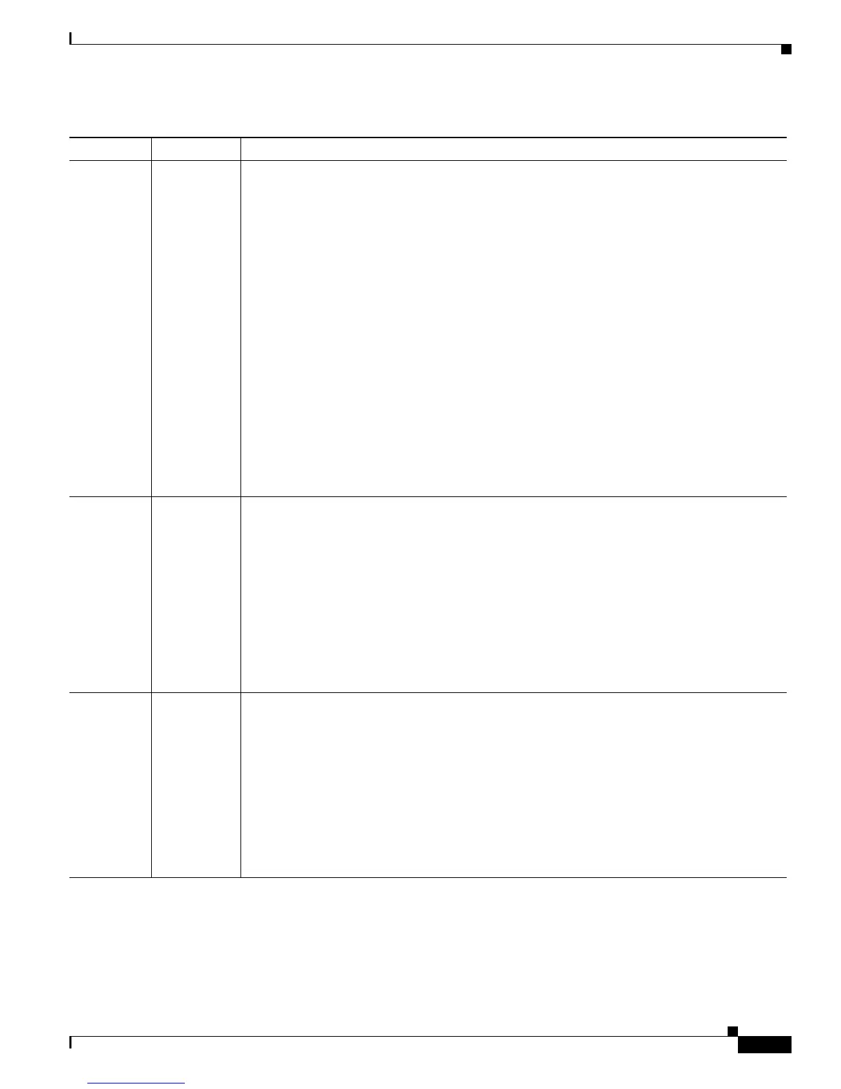
Table A-10 Cisco 3660 System Error and Status Messages (continued)
LED Type LED Color Message
 Loading...