3-14
Cisco 3700 Series Routers Hardware Installation Guide
OL-2180-08
Chapter 3 Installing the Router
Power Connections
Warning
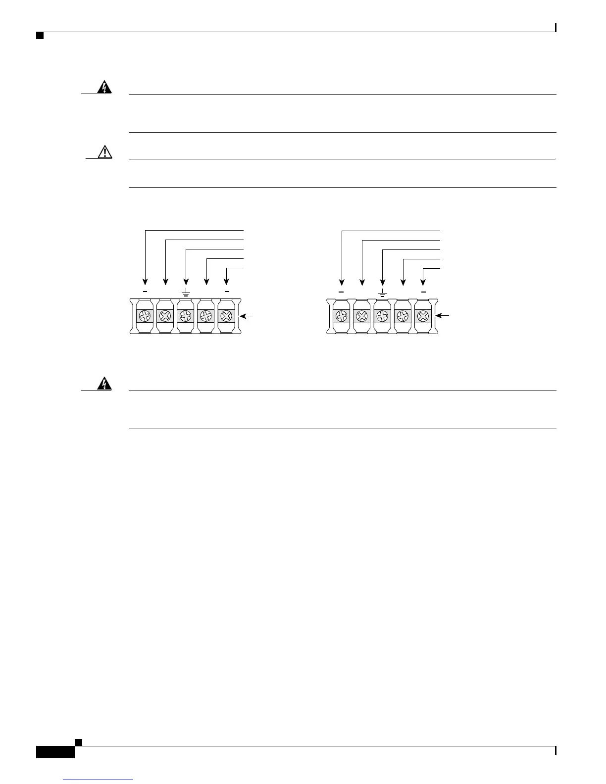
The illustration shows the DC power supply terminal block. Wire the DC power supply as illustrated.
The proper wiring sequence is ground to ground, positive to positive, and negative to negative. The
ground wire should always be connected first and disconnected last.
Statement 239
Caution Do not overtorque the terminal block contact screws. Recommended torque is 8.0 ± 0.5 in-lb
(0.9 ± 0.05 N-m).
Figure 3-16 DC Power Connections
Step 6 Install the plastic cover over the terminals. (See Figure 3-17.)
Warning
The safety cover is an integral part of the product. Do not operate the unit without the safety cover
installed. Operating the unit without the cover in place will invalidate the safety approvals and pose
a risk of fire and electrical hazards.
Statement
117
Step 7 Organize and secure the wires using cable ties as shown in Figure 3-17.
Step 8 Turn on power to the DC circuit.
95967
A
+
B
+
A ++B
Terminal
block
Negative DC input Positive DC input
Terminal
block
-DC, input B
Return, input B
Safety ground
Return, input A
-DC, input A
Return, input B
+DC, input B
Safety ground
+DC, input A
Return, input A

 Loading...