3-2
Cisco ASA 5500 Series Hardware Installation Guide
78-17374-01
Chapter 3 ASA 5510, ASA 5520, ASA 5540, and ASA 5550
Product Overview
Product Overview
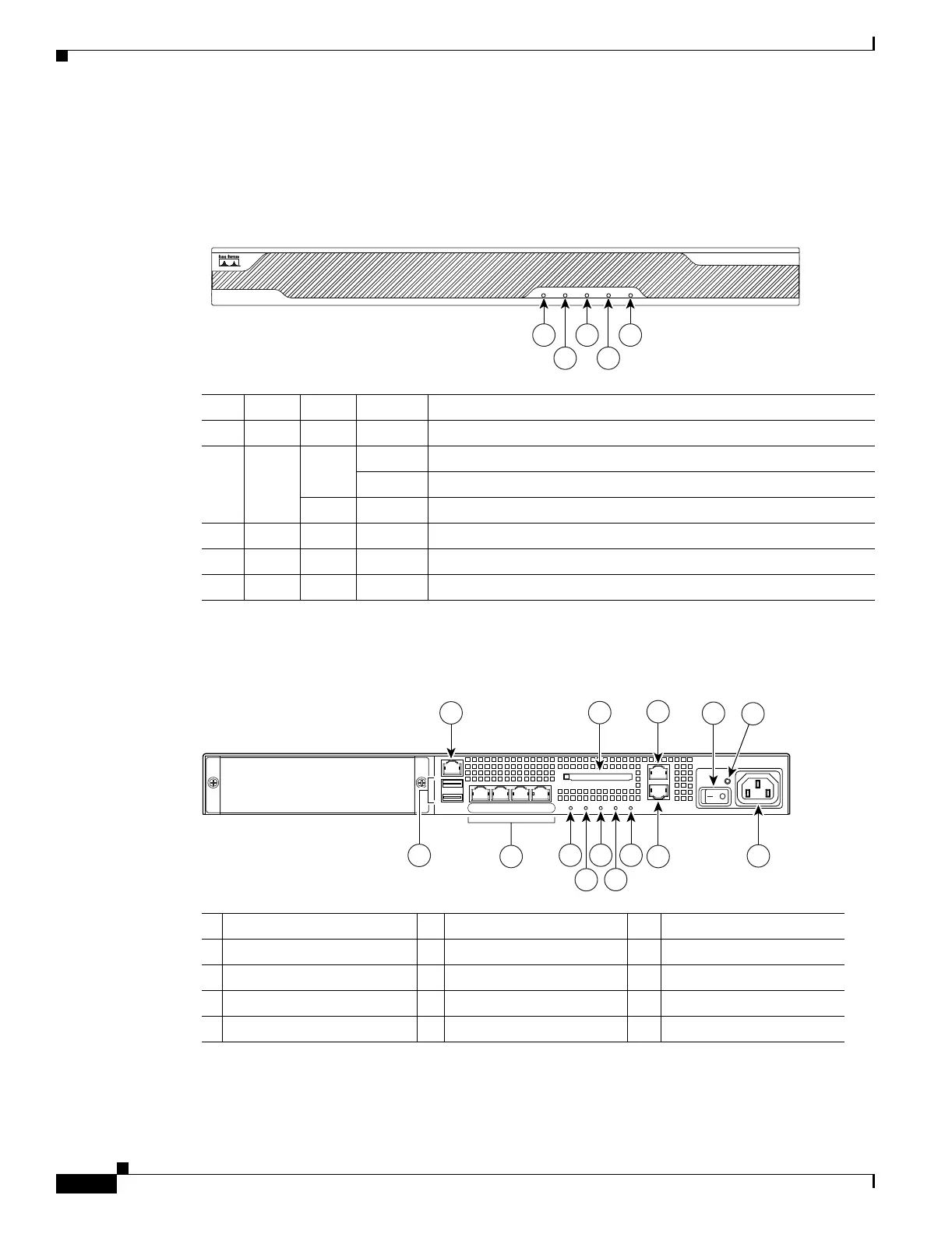
This section describes the front and rear panels. Figure 3-1 shows the front panel LEDs.
Figure 3-1 Front Panel LEDs
Figure 3-2 shows the rear panel.
Figure 3-2 Rear Panel LEDs and Ports (AC Power Supply Model Shown)
LED Color State Description
1 Power Green On The system has power.
2 Status Green Flashing The power-up diagnostics are running or the system is booting.
Solid The system has passed power-up diagnostics.
Amber Solid The power-up diagnostics have failed.
3 Active Green Flashing There is network activity.
4 VPN Green Solid VPN tunnel is established.
5 Flash Green Solid The CompactFlash is being accessed.
119638
POWER STATUS
FLASH
ACTIVE
VPN
CISCO ASA 5540
SERIES
Adaptive Security Appliance
1
2
3
4
5
1 Management port
1
1. The management 0/0 interface is a Fast Ethernet interface designed for management traffic only.
6 USB 2.0 interfaces
2
2. Not supported at this time.
11 VPN LED
2 External CompactFlash slot 7 Network interfaces
3
3. GigabitEthernet interfaces, from right to left, GigabitEthernet 0/0, GigabitEthernet 0/1, GigabitEthernet 0/2, and
GigabitEthernet 0/3.
12 Flash LED
3 Serial Console port 8 Power indicator LED 13 AUX port
4 Power switch 9 Status indicator LED 14 Power connector
5 Power indicator LED 10 Active LED
119572
LINK SPD
3
LINK SPD
2
LINK SPD
1
LINK SPD
0
MGMT
USB2
USB1
FLASH
CONSOLE
AUX
POWER
STATUS
FLASH
1
9
2
3
4
5
11
13
14
7
6
8 10 12
VPN
ACTIVE

 Loading...