B-2
Cisco ASA 5500 Series Hardware Installation Guide
OL-10089-01
Appendix B Maintenance and Upgrade Procedures
Removing and Replacing the Chassis Cover
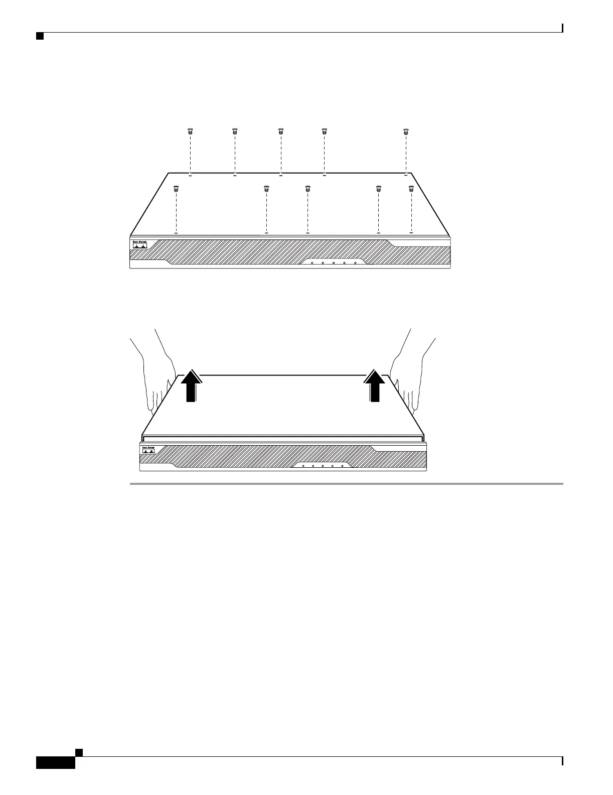
Step 3 Remove the screws from the top of the chassis (Figure B-1).
Figure B-1 Removing the Top Panel Screws
Step 4 Pull the top panel up as shown in Figure B-2. Put the panel in a safe place.
Figure B-2 Removing the Chassis Cover
119635
POWER STATUS
FLASH
ACTIVE
VPN
CISCO ASA 5540
SERIES
Adaptive Security Appliance
119636
POWER STATUS
FLASH
ACTIVE
VPN
CISCO ASA 5540
SERIES
Adaptive Security Appliance

 Loading...