1-2
Cisco 7600 Series Router Module Guide
OL-9392-05
Chapter 1 Modules Overview
Port Addresses
Port Addresses
Each port (or interface) in the router is designated by several different types of addresses. The physical
interface address is the actual physical location (slot and port) of the interface connector within the
chassis. The system software uses the physical addresses to control activity within the router and to
display status information. These physical slot and port addresses are not used by other devices in the
network; they are specific to the individual router and its internal components and software. For more
information, see the
“Physical Interface Addresses” section on page 1-2.
Note For Cisco 7600 series routers running Cisco IOS software, refer to the appropriate Cisco 7600 Series
Cisco IOS Software Configuration Guide, for port address information.
The Media Access Control (MAC) address is a standardized data link layer address that is required for
every port or device that connects to a network. Other devices in the network use these addresses to
locate specific ports in the network and to create and update routing tables and data structures. The
routers use a unique method, described in the
“MAC Addresses” section on page 1-3, to assign and
control the MAC addresses of their interfaces.
Physical Interface Addresses
Physical port addresses specify the actual physical location of each module port on the rear of the router,
as shown in
Figure 1-1. (The port numbering convention is the same in the 6-slot, 9-slot, and 13-slot
chassis.) The address is a two-part number in the format slot/port number. The first number identifies
the slot in which the module is installed. Module slots are numbered from top to bottom starting with
1.
The second number identifies the physical port number on the module. The port numbers always begin
at 1 and are numbered from left to right. The number of additional ports (n/1, n/2, and so on) depends
on the number of ports on the module.
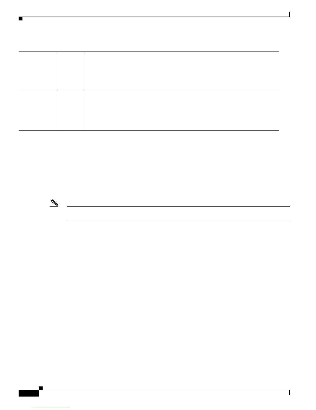
Red The diagnostic test failed. The module is not operational because a fault occurred during
the initialization sequence.
An overtemperature condition has occurred. (A major temperature threshold has been
exceeded during environmental monitoring.)
LINK Green The port is operational.
Orange The link has been disabled by software.
Flashing
orange
The link is bad and has been disabled due to a hardware failure.
Off No signal is detected.
Table 1-1 Router Module LEDs (continued)
LED Color/State Description

 Loading...


