1-7
Cisco Video Surveillance 8020/8030 IP Camera Reference Guide
Chapter 1 Getting Started
Hardware Installation
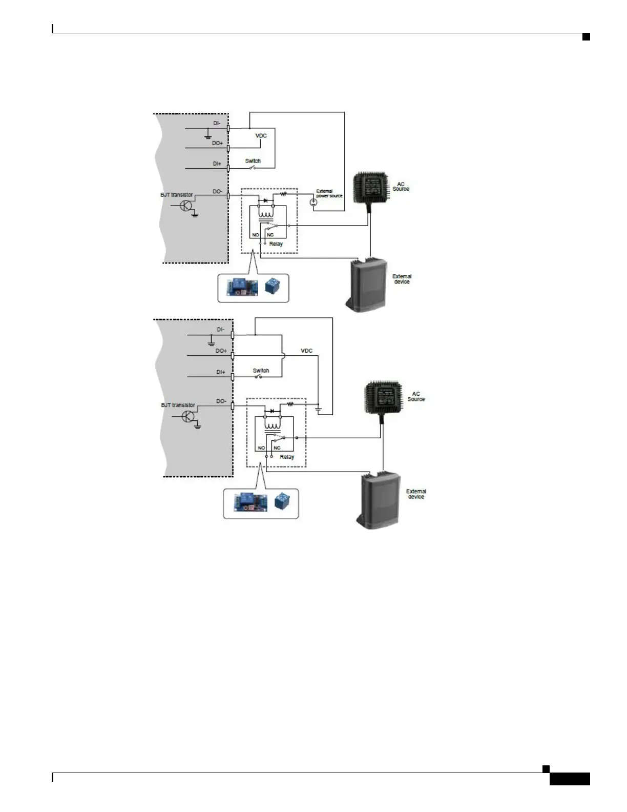
Here is the DI/DO Diagram:
• The DO+ pin provides 5V output voltage, and the max. load is 50mA.
• The max. voltage for DO- pins is 80VDC (External power). In order to control AC devices, the above
diagram can be taken in consideration. The diagram uses a relay to control the ON/OFF condition
of the AC device.
• An external relay can be triggered by using DO+ or by an external power source, depending on the
type of relay you use.
• In case of using an individual relay (instead of using a relay module), for protection against voltage
or current spikes, a transient voltage suppression diode must be connected in parallel with the
inductive load.
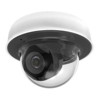
Step 6 Adjust the shooting direction by turning and orienting the lens module. Use a Phillips screwdriver to
loosen the retention screws on the sides.