Step 5 Position the phone so that the front of the phone faces up.
Step 6 Connect one end of the key expansion module spine connector to the accessory connector on the Cisco IP
Phone.
a) Align the spine connector with the accessory connector ports.
Install the connector in the orientation shown in the following diagrams.
Note
b) Firmly press the spine connector into the phone.
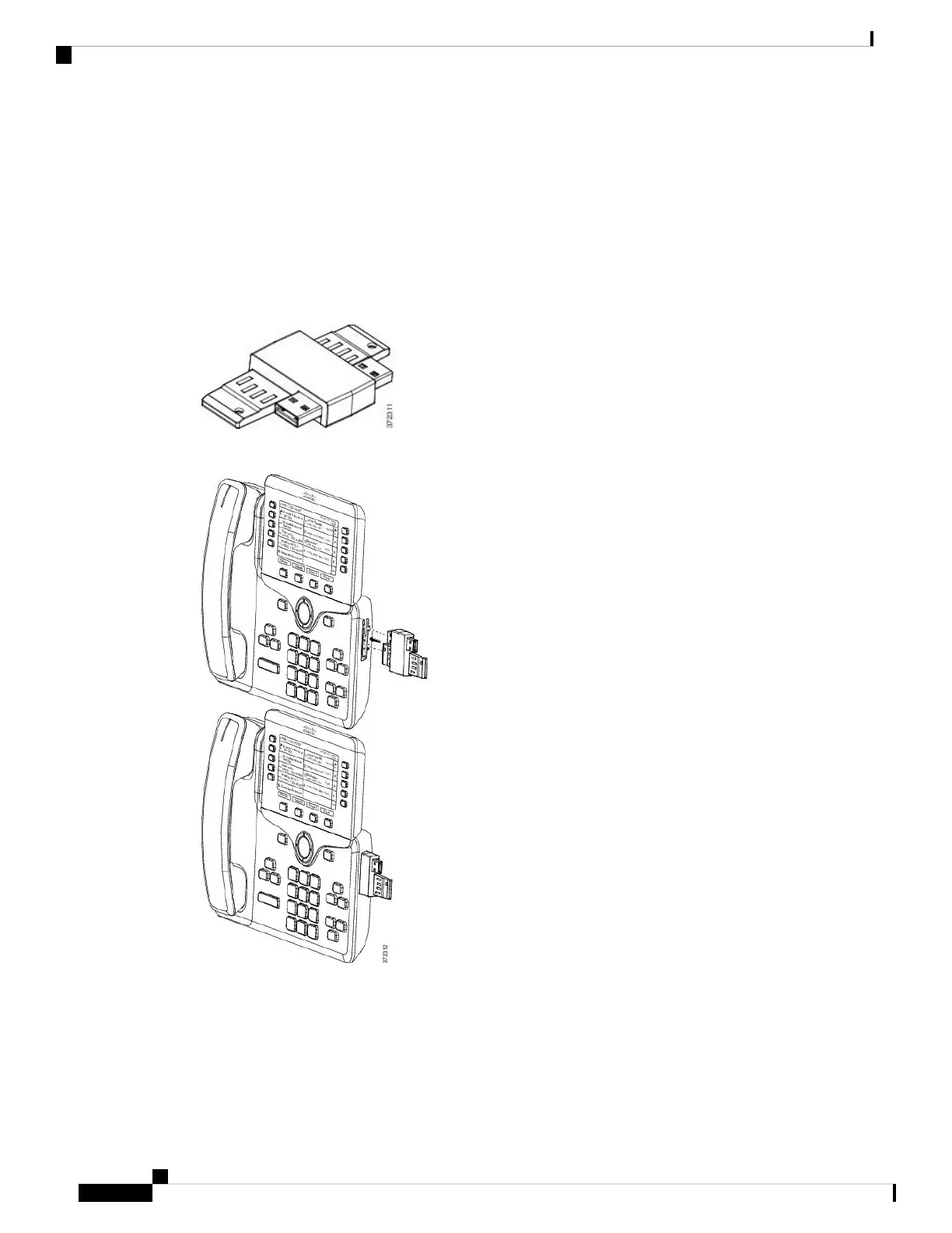
This diagram shows the spine connector.
This diagram shows the installation of the spine connector.
Step 7 Connect the other end of the spine connector to the key expansion module as shown in this diagram.
a) Align the spine connector with the key expansion module accessory connector ports.
b) Firmly press the key expansion module into the spine connector.
Cisco IP Phone 8800 Series Multiplatform Phones Administration Guide
112
Hardware and Accessory Installation
Connect a Key Expansion Module to a Cisco IP Phone
 Loading...