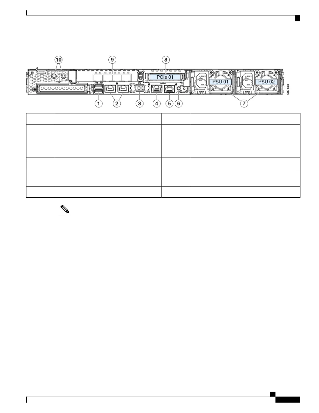
Figure 2: Cisco APIC M3 and L3 Server Rear Panel
Rear unit identification button/LED6USB 3.0 ports (two)1
Power supplies (two, redundant as 1+1)7Dual 1-Gb/10-Gb Ethernet ports (LAN1 and
LAN2)
The dual LAN ports can support 1 Gbps and 10
Gbps, depending on the link partner capability.
2
PCIe riser 1/slot 1 (x16 lane)8VGA video port (DB-15 connector)3
VIC 1455 with external 10/25-Gigabit Ethernet ports
(4)
91-Gb Ethernet dedicated management port4
Threaded holes for dual-hole grounding lug10Serial port (RJ-45 connector)5
The VIC 1455 has 4 ports, port-0, port-1, port-3, and port-4 from left to right.
Note
• All ports must have the same speed, either 10-Gigabit or 25-Gigabit.
• Port-0 and port-1 is one pair, corresponding to eth2-1 on APIC and port-2 and port-3 is another pair,
corresponding to eth2-2 on APIC. Only one connection is allowed for each pair. For example, you can
connect one cable to either port-0 or port-1, and connect another cable to either port-2 or port-3 (please
do not connect two cables on any pair).
Serviceable Component Locations
This topic shows the locations of the field-replaceable components and service-related items. The view in the
following figure shows the server with the top cover removed.
Cisco APIC M3/L3 Server Installation and Service Guide
3
Overview
Serviceable Component Locations