a) Ground lead wire (right)
b) Positive (+) lead wire (middle)
c) Negative (–) lead wire (left)
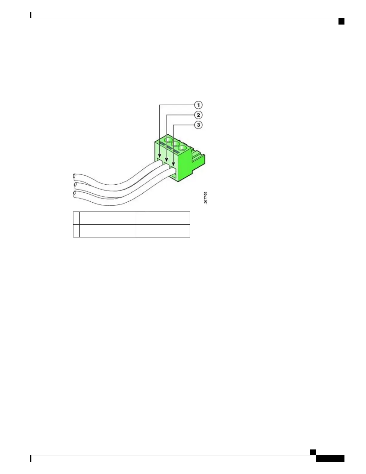
The following figure shows the DC power supply with lead wires.
Figure 82: DC Power Supply with Lead Wires
Ground lead wire3Negative (–) lead wire1
——Positive (+) lead wire2
Step 7 Insert the exposed wire of one of the ground wire into the terminal block plug. Make sure that you cannot see any wire
lead. Only wire with insulation should extend from the terminal block.
Do not overtorque the terminal block plug captive screws. The recommended maximum torque is from 0.5
Nm (4.425 lbf in.) to 0.6 Nm (5.310 lbf in.).
Caution
Step 8 Use a ratcheting torque screwdriver to torque the terminal block plug captive screw (above the installed wire lead) to
from 0.5 Nm (4.425 lbf in. to 0.6 Nm (5.310 lbf in.) as shown in the following figure.
Removing and Replacing FRUs from the Cisco ASR 1000 Series Routers
117
Removing and Replacing FRUs from the Cisco ASR 1000 Series Routers
Wiring the DC Input Power Source

 Loading...


