18
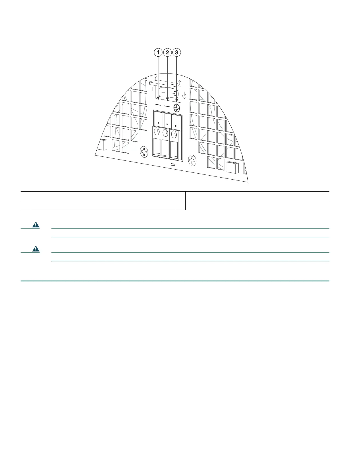
Figure 14 Cisco ASR 1002-X Router –48V DC Terminal Block
Warning
Never install an AC power module and a DC power module in the same chassis.
Statement 1050
Warning
Installation of the equipment must comply with local and national electrical codes.
Statement 1074
To connect
Step 1 At the rear of the router, check that the power supply Standby switch is in the Standby position.
Step 2 Ensure that the negative and positive leads are disconnected from the site power source and the circuit breaker is turned
off.
Step 3 Insert a –48V DC power supply in power supply slot 0 or power supply slot 1 until it is full seated.
Step 4 Using a wire stripper, strip approximately 0.55 inch (14 mm) from the negative, positive, and ground lead.
1
Negative lead
3
Earth ground symbol
2
Positive lead
280291

 Loading...


