43
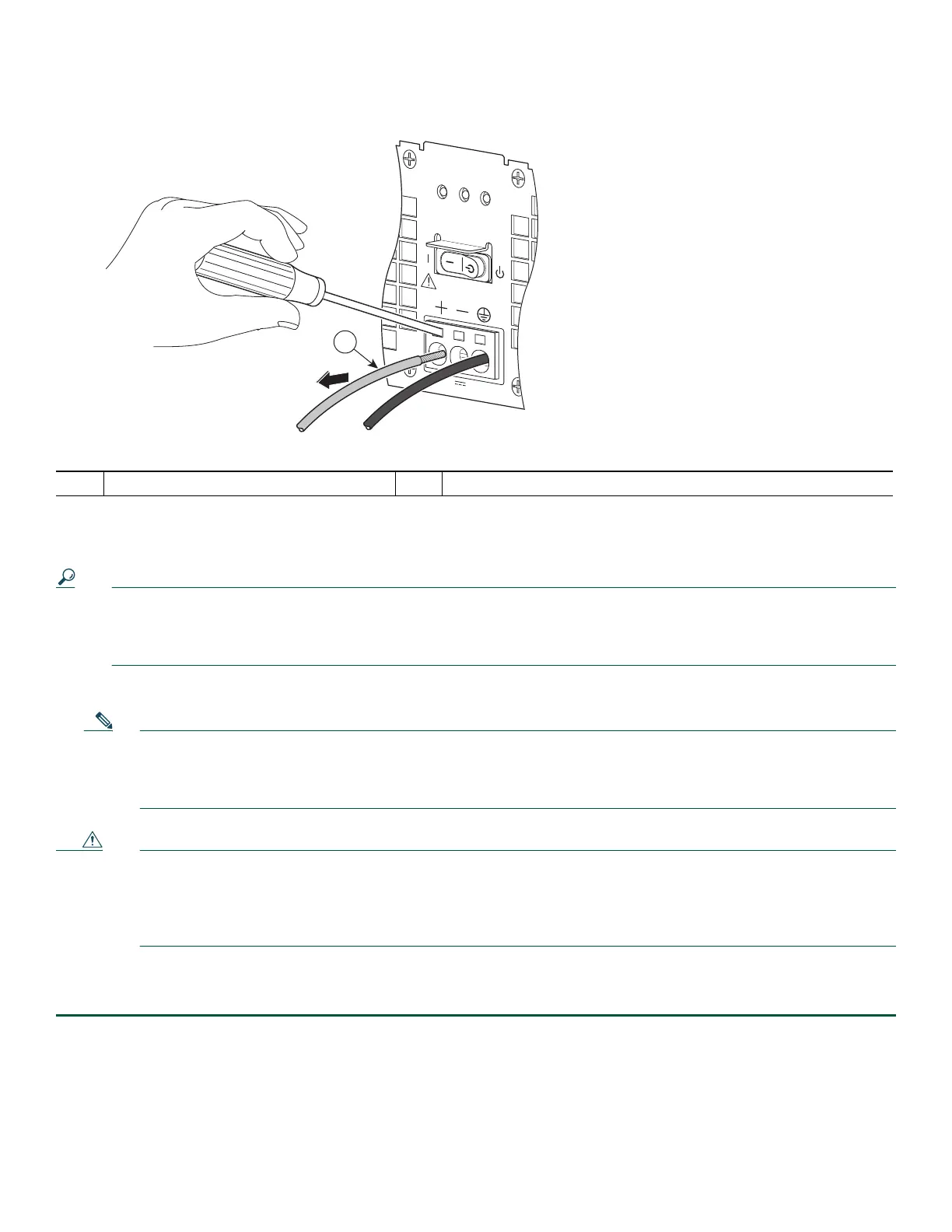
Figure 25 Removing the Cisco ASR 1002-X Router +24V DC Power Supply Lead Wires
Step 4 Remove the screwdriver and continue removing the remaining lead wires from the terminal block, repeating Step 3 and
Step 4 for each lead wire.
Tip If the 8-gauge input wiring is very rigid or a solid wire, then a screwdriver might not be necessary. As a result of using
few-strand heavy gauge wiring, you can insert the wire into the terminal block to release the spring tension. After
inserting the lead wire, gently pull on the wire to make certain that the wire is secured. Make certain that no wire is
exposed and that only wire insulation is seen.
Step 5 Unscrew the two power supply captive screws.
Note Four power supplies must be installed in the chassis at all times, with a minimum of two power supplies (one per
zone) connected to the mains in order to power on the system and ensure sufficient cooling. The system fans are
inside the power supply units and must spin for cooling. Because all the system fans can be powered by one power
supply, the second power supply unit does not have to be powered on, but must be connected.
Caution If you remove a power supply from a system that has four power supplies that are connected and powered on, the
system can run only for a maximum of five minutes before shutting down. However, because the fans and power
elements are independent within the power supply, the replacement power supply does not have to be energized
within five minutes. The only requirement is that the power supply be installed in the chassis in order to energize
the fans and maintain proper system cooling.
Step 6 Grasping the power supply handles, pull the power supply from the chassis.
Step 7 Replace the +24V DC power supply within five minutes.
You have completed the procedure for removing a +24V DC power supply from the Cisco ASR 1002-X Router. For replacing
the +24V DC power supply into the Cisco ASR 1002-X Router, see Connecting +24V DC Power to the Cisco ASR 1002-X
Router, page 20.
1 Pull lead wire out from terminal
OUTPUT INPUT
FAIL
OK OK
FAN
This unit might have more than
one power supply connection.
All connections must be removed
to de-energize the unit.
+27V DC INPUT
+27V 32A
1
253178

 Loading...


