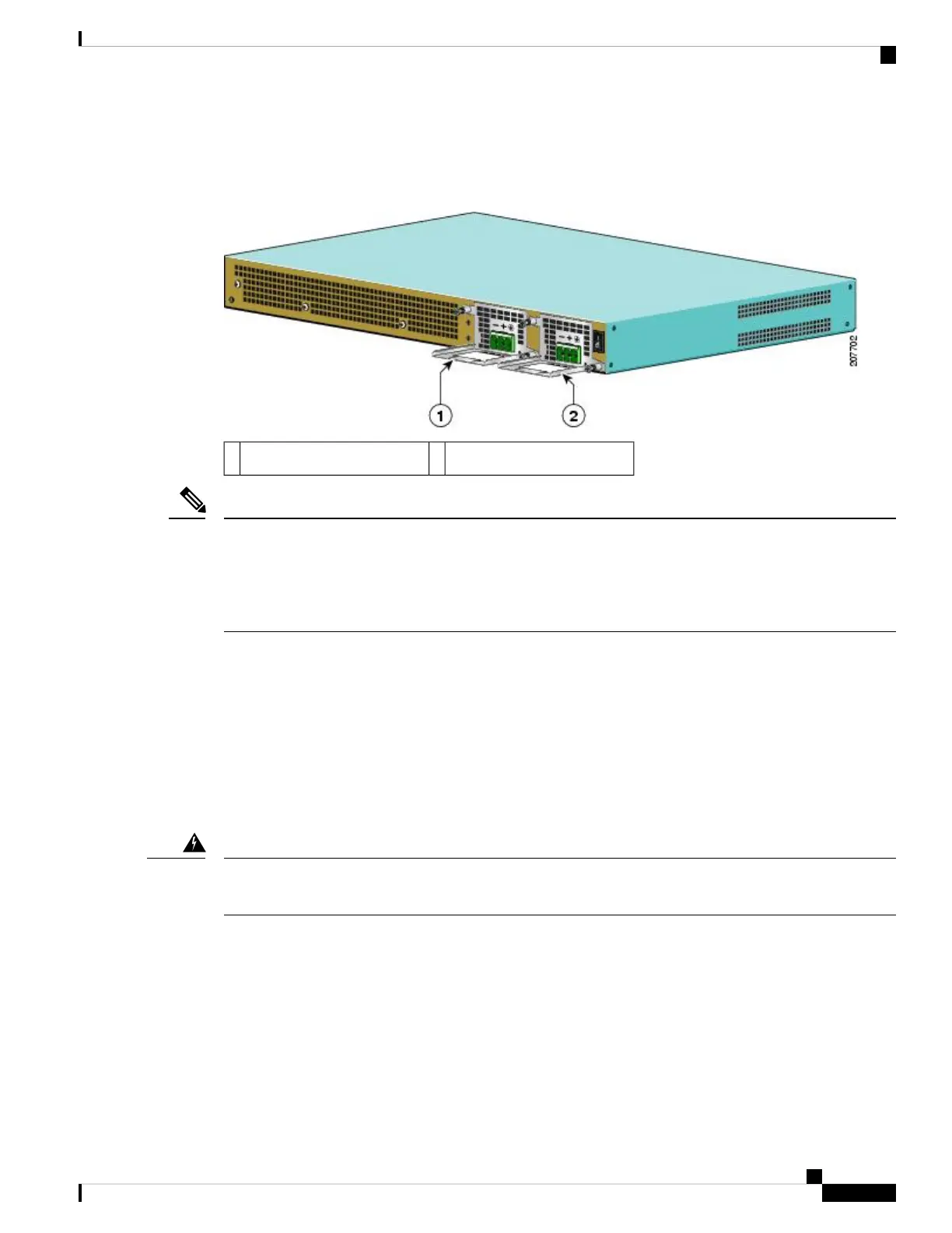
The power supply has a handle, to assist in insertion and extraction. The module must be supported with one
hand because of its length. The following figure shows the Cisco ASR 1001 Router DC power supply.
Figure 79: Cisco ASR 1001 Router DC Power Supply Rear View
DC power supply in slot PS12DC power supply in slot PS01
Two types of DC connector plugs are supported for use with the DC power supply for the Cisco ASR 1001
Router. In one type of connector plug, the screw holes are raised above the connector plug body. In the second
type, the screw holes are not raised above the connector plug body. xref fig shows the connector plug in which
the screw holes are not raised. The only difference in the method for using these two types of connector plugs
is related to the wire-strip length, which is mentioned later in this section.
Note
This section describes how to install the DC power supply ground leads and input power leads to the Cisco
ASR 1001 Router DC input power supply. Before you begin, read these important notices:
• The color coding of the DC input power supply leads depends on the color coding of the DC power
source at your site. Typically, green or green/yellow is used for ground (GND), black is used for –48 V
on negative (–) terminal and red is used for RTN on the positive (+) terminal. Make certain the lead color
coding you choose for the DC input power supply matches lead color coding used at the DC power
source.
• Make certain that the chassis ground is connected on the chassis before you begin installing the DC
power supply. Follow the steps in the xref “Attaching a Chassis Ground Connection” section.
When you install a power supply unit, the ground connection should always be made first and disconnected
last. Statement 1046
Warning
To connect the DC power supply on the Cisco ASR 1001 Router, follow these steps:
SUMMARY STEPS
1. Make certain that the chassis ground is connected on the chassis before you begin installing the DC power
supply as shown in the xref “Attaching a Chassis Ground Connection” section.
2. On the rear of the chassis next to the power supply bay PS1 as shown in the figure on page 5, make certain
the power supply switch is in Standby position.
3. Turn off the circuit breaker to the power supply.
Removing and Replacing FRUs from the Cisco ASR 1000 Series Routers
113
Removing and Replacing FRUs from the Cisco ASR 1000 Series Routers
Installing DC Power Supply into Cisco ASR 1001 Router
 Loading...


