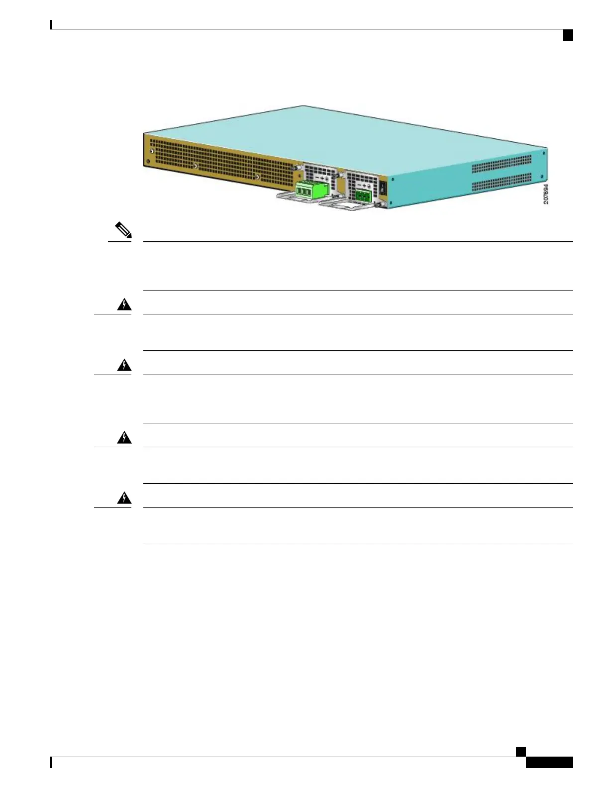
Figure 80: Cisco ASR 1001 Router DC Power Supply Terminal Block With a Connector Plug in Slot PS01 and Without a Plug in PS0
The color coding of the DC input power supply leads depends on the color coding of the DC power source
at your site. Make certain the lead color coding you choose for the DC input power supply matches lead color
coding used at the DC power source.
Note
When installing or replacing the unit, the ground connection must always be made first and disconnected last.
Statement 1046
Warning
This product relies on the building’s installation for short-circuit (overcurrent) protection. Ensure that the
protective device is rated not greater than: 120 VAC, 20A U.S. (240 VAC, 10A international). Statement
1005
Warning
Before performing any of the following procedures, ensure that power is removed from the DC circuit.
Statement 1003
Warning
Only trained and qualified personnel should be allowed to install, replace, or service this equipment. Statement
1030
Warning
Use the information in this section to wire the DC input power source.
SUMMARY STEPS
1. At the front of the router, make sure the power switch is in the standby (|) position.
2. Move the circuit-breaker switch handle to the off position, and apply tape to hold it in the off position.
3. Gather the DC power supply terminal block plug.
4. Insert the lead wires before inserting the plug into the terminal block header on the DC power supply.
5. Use a 10 gauge wire-stripping tool to strip each of the three wires coming from the DC input power
source. If you are using the connector plug with the raised screw holes, strip the wires to 0.39 inch (10
mm) + 0.02 inch (0.5 mm). If you are using the connector plug with the screw holes that are not raised,
strip the wires to 0.27 inch (7 mm) + 0.02 inch (0.5 mm). Do not strip more than the recommended
Removing and Replacing FRUs from the Cisco ASR 1000 Series Routers
115
Removing and Replacing FRUs from the Cisco ASR 1000 Series Routers
Wiring the DC Input Power Source
 Loading...


