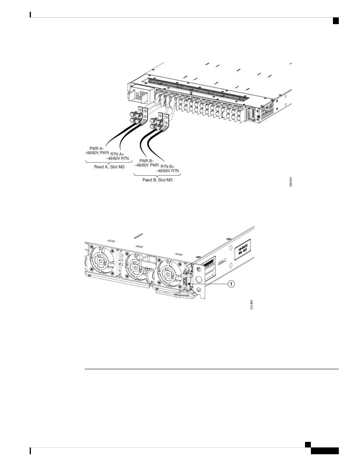
Figure 196: Typical Power Connections to a Power Tray for a Single DC Power Module—Version 3 Power System
Figure 197: Location of DC Power Switch—Version 2 and Version 3 Power System
a. Power switch
Step 5 Replace the clear plastic safety covers over the connection terminal studs. Step 6 shows the plastic safety
cover being installed over the version 2 DC power tray connection terminals. The plastic covers for the version
2 DC power tray are similar.
Step 6 Proceed to Powering On the Router, on page 195.
Powering On the Router
Follow these steps to turn on power to an AC-powered or DC-powered router:
Cisco ASR 9000 Series Aggregation Services Router Hardware Installation Guide
195
Installing Cards and Modules in the Chassis
Powering On the Router
 Loading...


