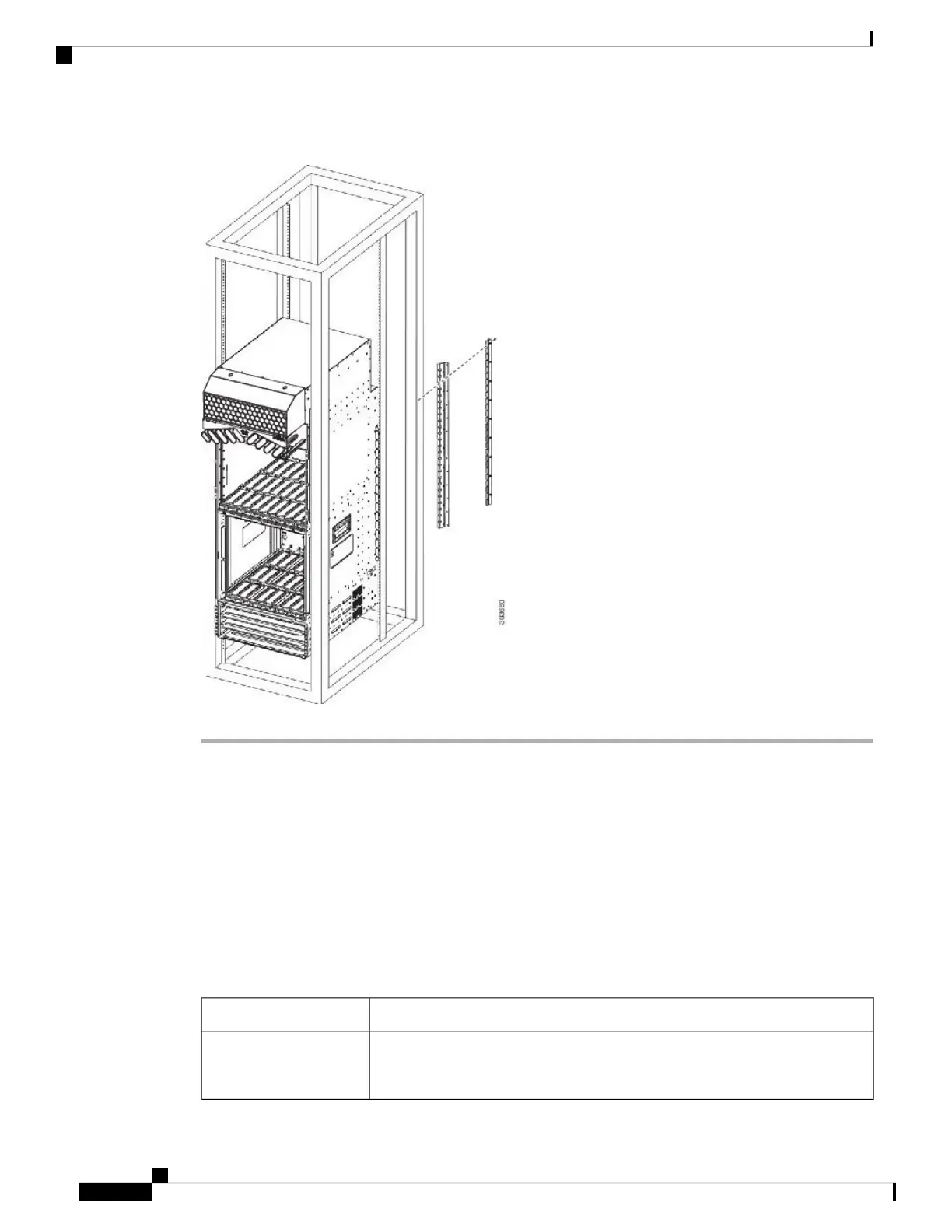
Figure 61: Installing the Cisco ASR 9922 Router Chassis in a 4-Post Rack
Supplemental Bonding and Grounding Connections
Before you connect power to the router, or power on the router for the first time, we recommend that you
connect the central office ground system or Network Equipment Building System (NEBS) to the threaded
supplemental bonding and grounding receptacles on the router. For more information on supplemental bonding
and grounding cable requirements, see NEBS Supplemental Unit Bonding and Grounding Guidelines, page
1-60 .
The table below references the grounding receptacle locations for the Cisco ASR 9000 Series Routers.
Table 3: Grounding Receptacle Locations
Grounding Receptacle LocationModel Number
Bottom rear right side of the chassis (Figure 62: NEBS Bonding and Grounding
for the Cisco ASR 9010 Router, on page 65).
Cisco ASR 9010 Router
and Cisco ASR 9910
Router
Unpacking and Installing the Chassis
64
Unpacking and Installing the Chassis
Supplemental Bonding and Grounding Connections

 Loading...


