EasyManuals Logo

Cisco ASR 9010 Unpacking And Installing

Cisco ASR 9010
98 pages
To Next Page IconTo Next Page
To Previous Page IconTo Previous Page
Page #72 background imageLoading...
Page #72 background image
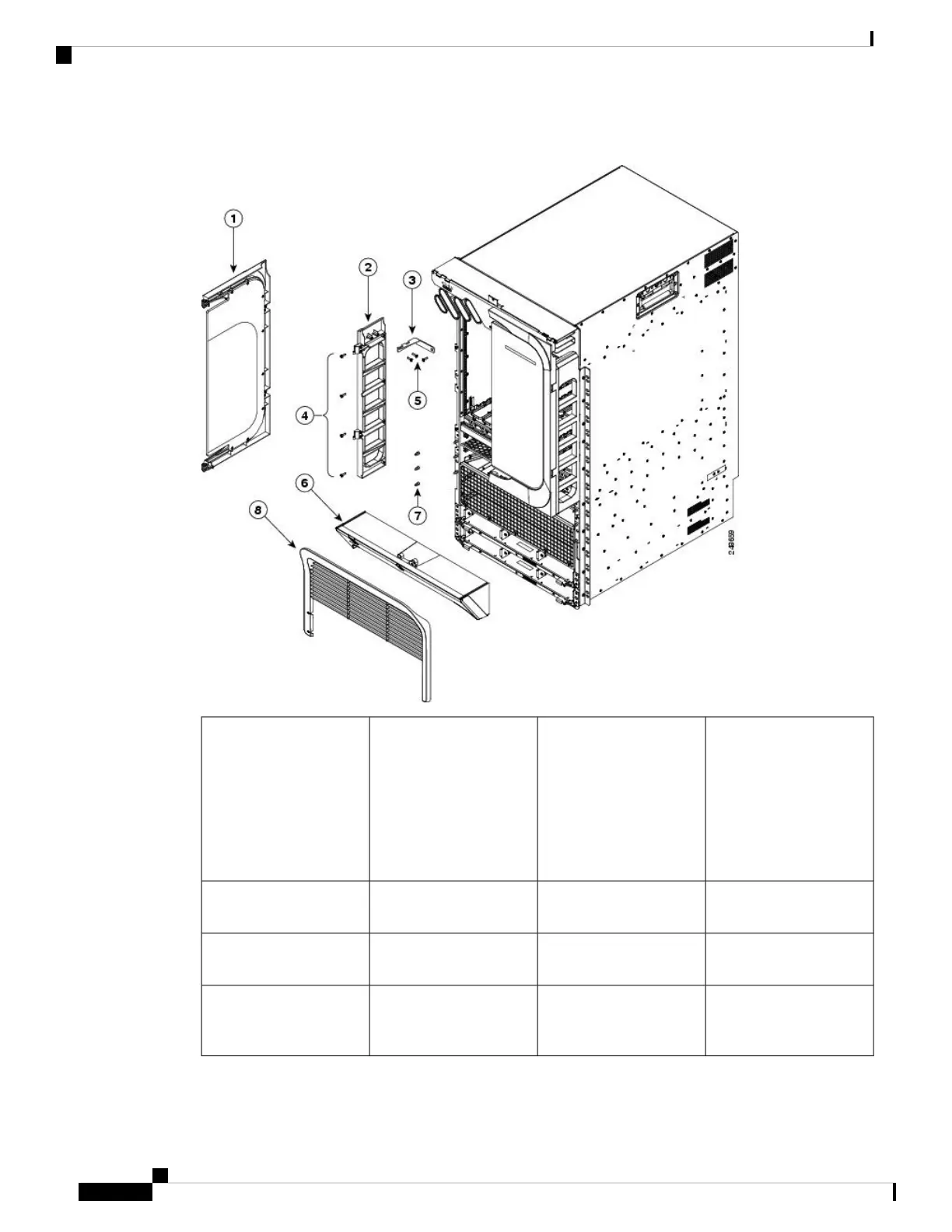
Figure 70: Optional Chassis Accessories for the Cisco ASR 9010 Router
Screws for attaching the
L-shaped bracket to the
hinge bracket (one screw
is removed and re-inserted
to attach the L-shaped
bracket to the cable
management tray and
chassis)
5Door (one per side)1
Mid-cover with door lock6Hinge bracket (one per
side)
2
Balls studs (three per side)7L-shaped bracket (one per
side)
3
Front grill8Four screws for attaching
each hinge bracket (eight
screws total)
4
Unpacking and Installing the Chassis
72
Unpacking and Installing the Chassis
Installing Optional Chassis Accessories on the Cisco ASR 9010 Router

Table of Contents

Other manuals for Cisco ASR 9010

Questions and Answers:

Question and Answer IconNeed help?

Do you have a question about the Cisco ASR 9010 and is the answer not in the manual?

Cisco ASR 9010 Specifications

General IconGeneral
ChassisModular
Rack Units21 RU
Operating SystemCisco IOS XR
Form FactorRack-mountable
Number of Slots10
Power SupplyAC or DC
RedundancyYes
Slots8 line card slots, 2 route switch processor slots
Memory16 GB DRAM
Storage64 GB SSD (Route Processor)
Port TypesEthernet, OTN
Redundancy FeaturesRoute Processor, Power Supply, Fan Tray
Operating Temperature32 to 104°F (0 to 40°C)
Humidity5% to 90% non-condensing
Route ProcessorCisco ASR 9000 Series Route Switch Processor

Related product manuals