Cisco ASR 903 Router Design and Deployment Guide▄
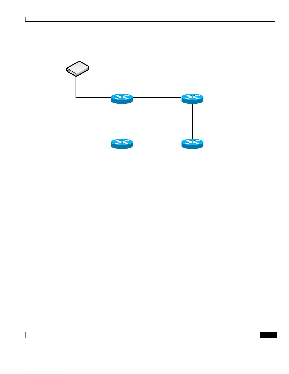
Figure 31. PTP
ASR903-R2(BC)
Loopback10: 10.10.2.2
ASR903-R4(Slave)
Loopback10: 10.10.4.4
Gi0/1/0
Gi0/1/0
Gi0/1/1
Gi0/1/1
Gi0/1/0Gi0/1/2
Gi0/1/0Gi0/1/1
Gi0/1/4
ASR903-R3(TC)
Loopback10: 10.10.3.3
ASR903-R1(BC)
Loopback10: 10.10.1.1
Clock Source – TP5k
IP: 192..168.2..11
Gi0/1/3
ASR903-R1 Configuration
interface Loopback10 ! use seperate interfaces for master and
slave
ip address 10.10.1.1 255.255.255.255
!
interface Loopback11
ip address 10.10.158.1 255.255.255.255
!
network-clock synchronization automatic
network-clock synchronization mode QL-enabled
network-clock input-source 10 ptp domain 0 ! specify PTP as clock source
!
ptp clock boundary domain 0
clock-port TPSlave slave ! upstream master and itself slave
transport ipv4 unicast interface Lo10 negotiation
clock source 192.168.2.11 ! upstream master IP address
clock-port Master master ! master for the downstream slaves
transport ipv4 unicast interface Lo11 negotiation

 Loading...


