Step 4
Identify the positive and negative feed positions for the terminal block. The recommended wiring sequence is as in the
figure below.
Step 5
Attach the lugs on the terminal block, see the figure below.
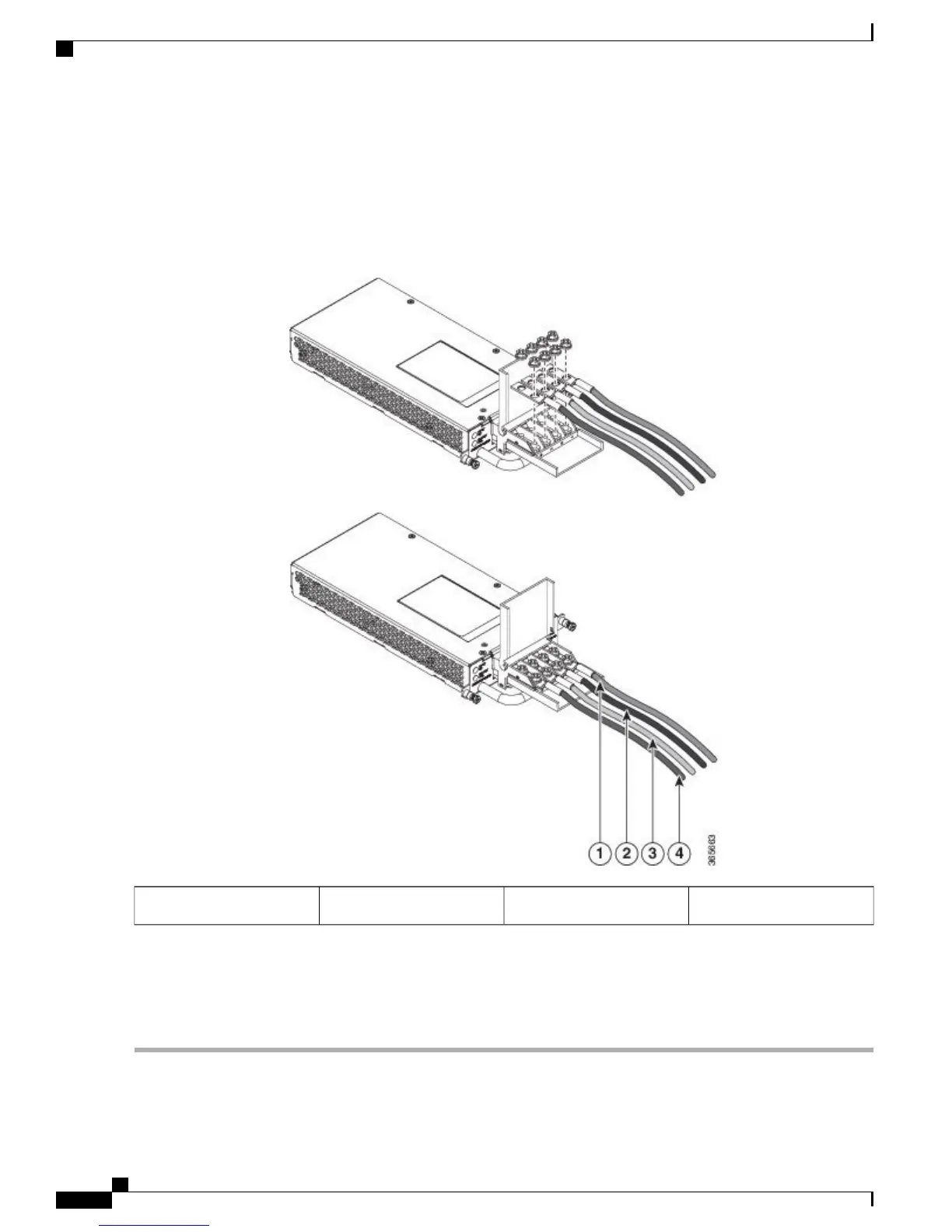
Figure 27: Power Supply with Lead Wires
Negative (-) lead wire2, 4Positive (+) lead wire1, 3
Do not overtorque the fasteners of the terminal block. The recommended maximum torque is from 25 in.-lb
(2.82 N-m).
Caution
Step 6
Use a tie wrap to secure the wires to the rack, so that the wires are not pulled from the terminal block by casual contact.
Make sure the tie wrap allows for some slack in the wire.
Cisco ASR 903 and ASR 903U Aggregation Services Router Hardware Installation Guide
36
Installing the Cisco ASR 903 Router
Installing the DC Power Supply

 Loading...


