1-15
Cisco ASR-920-24SZ-IM, ASR-920-24SZ-M, ASR-920-24TZ-M Aggregation Services Router Hardware Installation Guide
Chapter 1 Overview
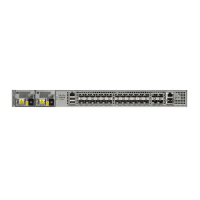
Cisco ASR 920 Series Routers Features
SFP LEDs
Each SFP port has an LED indicator. The LED is configured such that the up arrow indicates the port on
the upside and the down arrow indicates the port on the downside.
SFP+ LEDs
Each SFP+ port has an LED indicator.
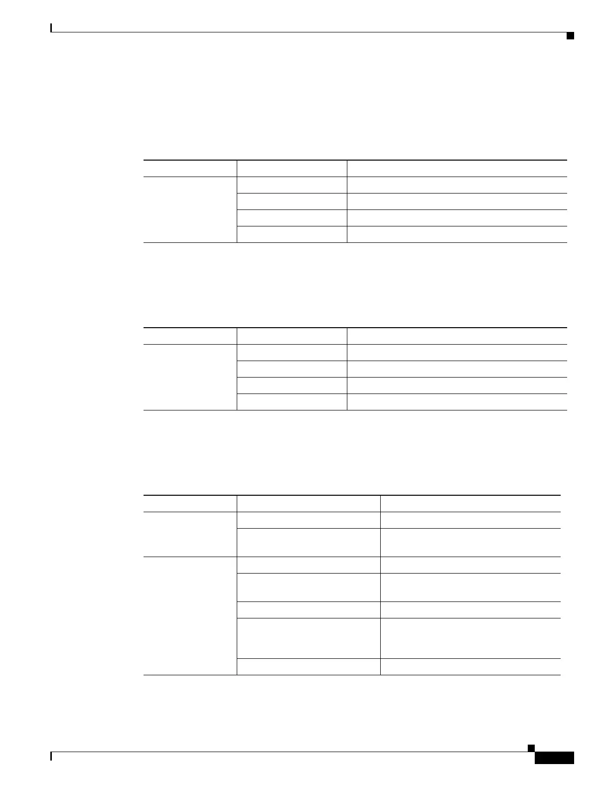
8 T1/E1 Interface Module LEDs
Table 1-9 summarizes the LEDs for the 8 x T1/E1 interface module.
Table 1-7 SFP Port LED Indication
LED LED State Indication
Labeled same as the
SFP port number
Green Link up in 1000Base-X/100Base-FX
Blinking Green Activity in 1000 Base-X/100Base-FX
Yellow Fault/Error
Off Link down
Table 1-8 SFP+ Port LED Indication
LED LED State Indication
Labeled same as the
SFP port number
Green Link up in 10G
Blinking Green Activity in 10G
Yellow Fault/Error
Off Link down
Table 1-9 8 x T1/E1 Interface Module LEDs
LED LED State Indication
Active Green Active
Off Operationally down; card is disabled or
shut down
Port Green All ports up
Blinking green All ports up and one or more ports in a
loopback state
Amber One or more configured ports are down
Blinking amber One or more configured ports are down
and at least one configured port is in a
loopback state
Off All ports disabled or shut down
 Loading...