1-16
Cisco ASR-920-24SZ-IM, ASR-920-24SZ-M, ASR-920-24TZ-M Aggregation Services Router Hardware Installation Guide
Chapter 1 Overview
Cisco ASR 920 Series Routers Features
RJ-45 LEDs
Each RJ-45 port has two LED indicators. Left LED indicates the Link status; right LED indicates the
status of the duplex LED.
Power Supply Unit LEDs
Each power supply unit has a corresponding LED on the front panel.
Power
(PWR)
Green All power rails are within supported range
Red Disabled
Off No power to the Interface Module
Operating Status
(STAT)
Red Failed
Off Disabled or powered-down
Blinking red Booting
Green Active
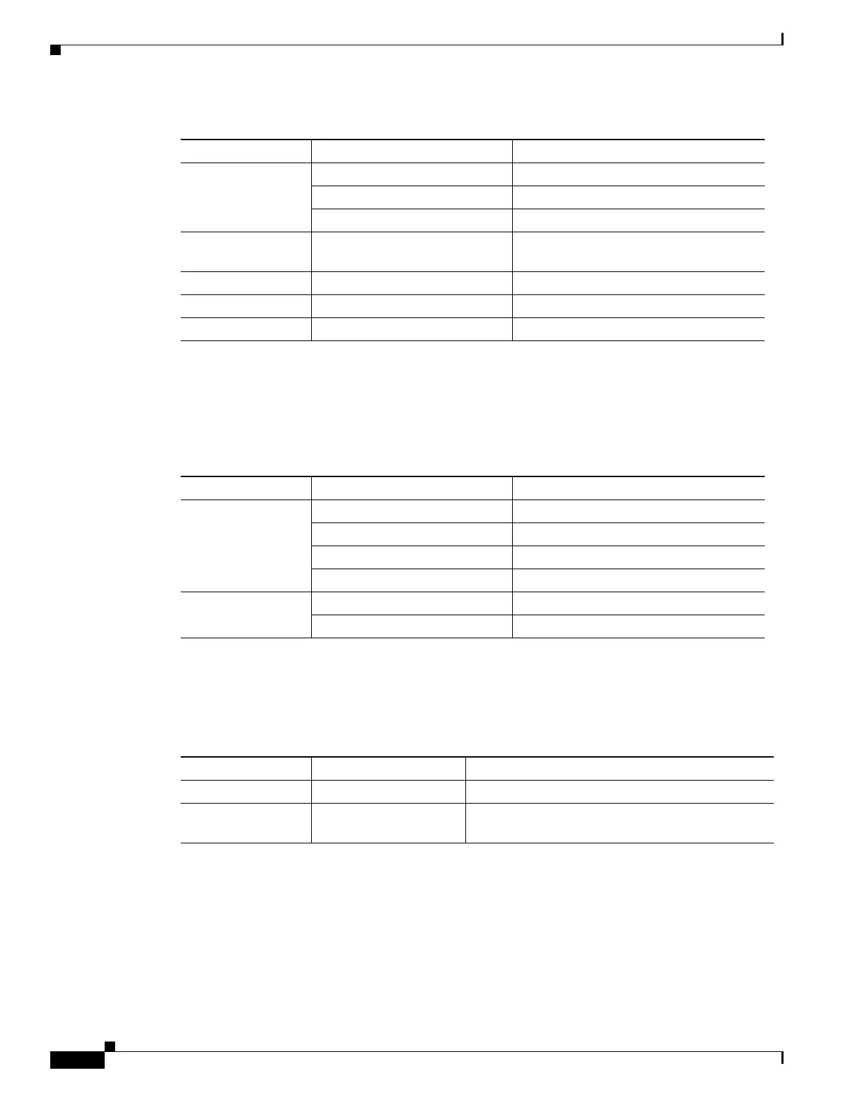
Table 1-9 8 x T1/E1 Interface Module LEDs
LED LED State Indication
Table 1-10 RJ-45 LED Indication
LED LED State Indication
Left Green Link up in 10/100/1000Base-T
Blinking Green Activity in 10/100/1000Base-T
Yellow Fault/Error
Off Link down
Right Green Link up in full duplex
Off Link up in half duplex
Table 1-11 PSU LED Indication
LED LED State Indication
OK Green Power Supply is working and 12V output is alright.
Red 12V output failure (Either input not present or fault
in the power supply unit).
 Loading...