3-3
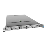
Cisco UCS C240 M4 Server Installation and Service Guide
OL-32474-01
Chapter 3 Maintaining the Server
Status LEDs and Buttons
Table 3-1 Front Panel LEDs, Definitions of States
LED Name State
1 Hard drive fault
Note: If your controller is a Cisco
UCS RAID SAS 9300-8i or
9300-8e HBA, see Cisco UCS
SAS 9300-8e HBA
Considerations, page C-4 for
differing LED behavior.
• Off—The hard drive is operating properly.
• Amber—Drive fault detected.
• Amber, blinking—The device is rebuilding.
• Amber, blinking with one-second interval—Drive locate function activated.
2 Hard drive activity
• Off—There is no hard drive in the hard drive tray (no access, no fault).
• Green—The hard drive is ready.
• Green, blinking—The hard drive is reading or writing data.
3 Power button/LED
• Off—There is no AC power to the server.
• Amber—The server is in standby power mode. Power is supplied only to the
Cisco IMC and some motherboard functions.
• Green—The server is in main power mode. Power is supplied to all server
components.
4 Unit Identification
• Off—The unit identification function is not in use.
• Blue—The unit identification function is activated.
5 System status
• Green—The server is running in a normal operating condition.
• Green, blinking—The server is performing system initialization and memory
check.
• Amber, steady—The server is in a degraded operational state. For example:
–
Power supply redundancy is lost.
–
CPUs are mismatched.
–
At least one CPU is faulty.
–
At least one DIMM is faulty.
–
At least one drive in a RAID configuration failed.
• Amber, blinking—The server is in a critical fault state. For example:
–
Boot failed.
–
Fatal CPU and/or bus error is detected.
–
Server is in an over-temperature condition.
6 Fan status
• Green—All fan modules are operating properly.
• Amber, steady—One or more fan modules breached the critical threshold.
• Amber, blinking—One or more fan modules breached the non-recoverable
threshold.