3-8
Cisco UCS C240 M4 Server Installation and Service Guide
OL-32474-01
Chapter 3 Maintaining the Server
Status LEDs and Buttons
Internal Diagnostic LEDs
The server is equipped with a supercap voltage source that can activate internal component fault LEDs
up to 30 minutes after AC power is removed. The server has internal fault LEDs for CPUs, DIMMs, fan
modules, SD cards, the RTC battery, and the mLOM card.
To use these LEDs to identify a failed component, press the front or rear Unit Identification button (see
Figure 3-1 or Figure 3-2) with AC power removed. An LED lights amber to indicate a faulty component.
See Figure 3-3 for the locations of these internal LEDs.
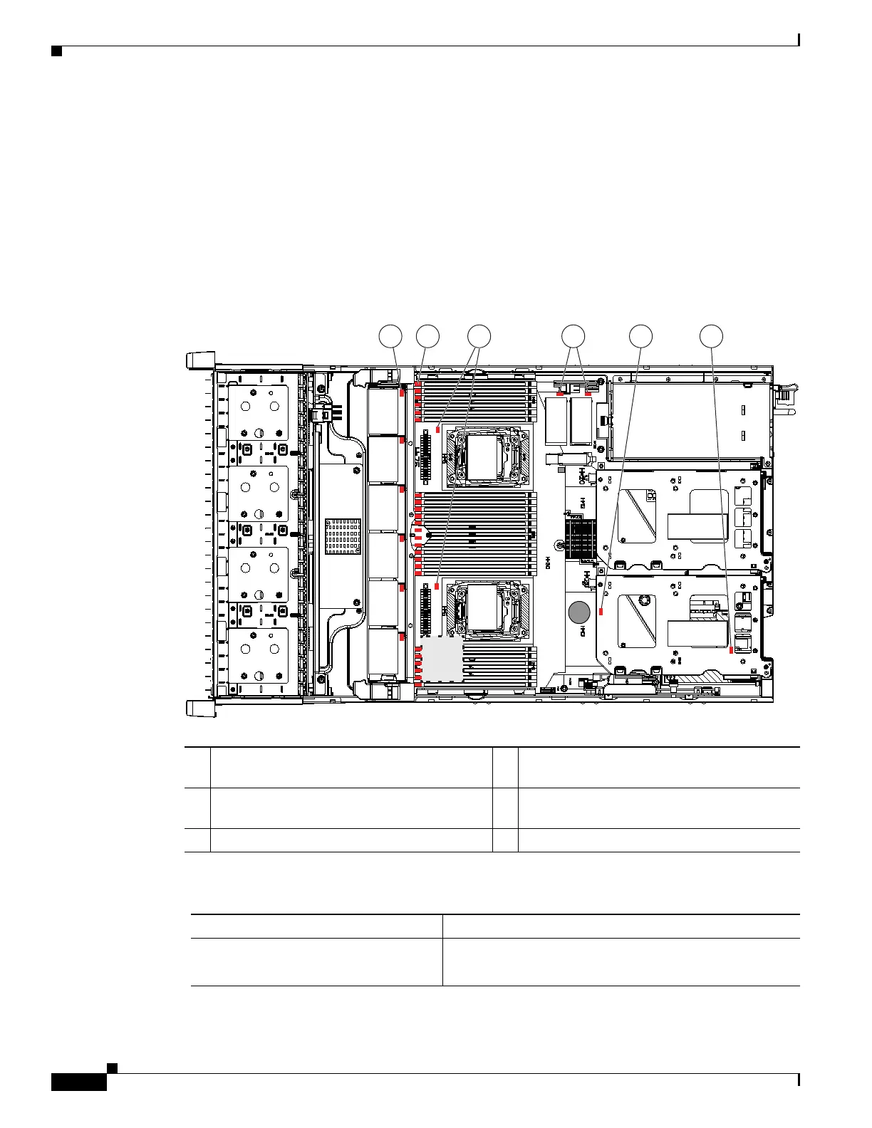
Figure 3-3 Internal Diagnostic LED Locations
1 Fan module fault LEDs (one on each fan
module)
4 SD card fault LEDs
2 DIMM fault LEDs (one directly in front of
each DIMM socket on the motherboard)
5 RTC battery fault LED (under PCIe riser 1)
3 CPU fault LEDs 6 mLOM card fault LED (under PCIe riser 1)
Table 3-4 Internal Diagnostic LEDs, Definition of States
LED Name State
Internal diagnostic LEDs (all)
• Off—Component is functioning normally.
• Amber—Component has a fault.
352952
FAN 06
1
2
3
FAN 05
FAN 04
FAN 03
FAN 02
FAN 01
CPU 1
CPU 2
SD1
SD2
Riser 2
Riser 1
4 65