3-7
Cisco UCS C240 M4 Server Installation and Service Guide
OL-32474-01
Chapter 3 Maintaining the Server
Status LEDs and Buttons
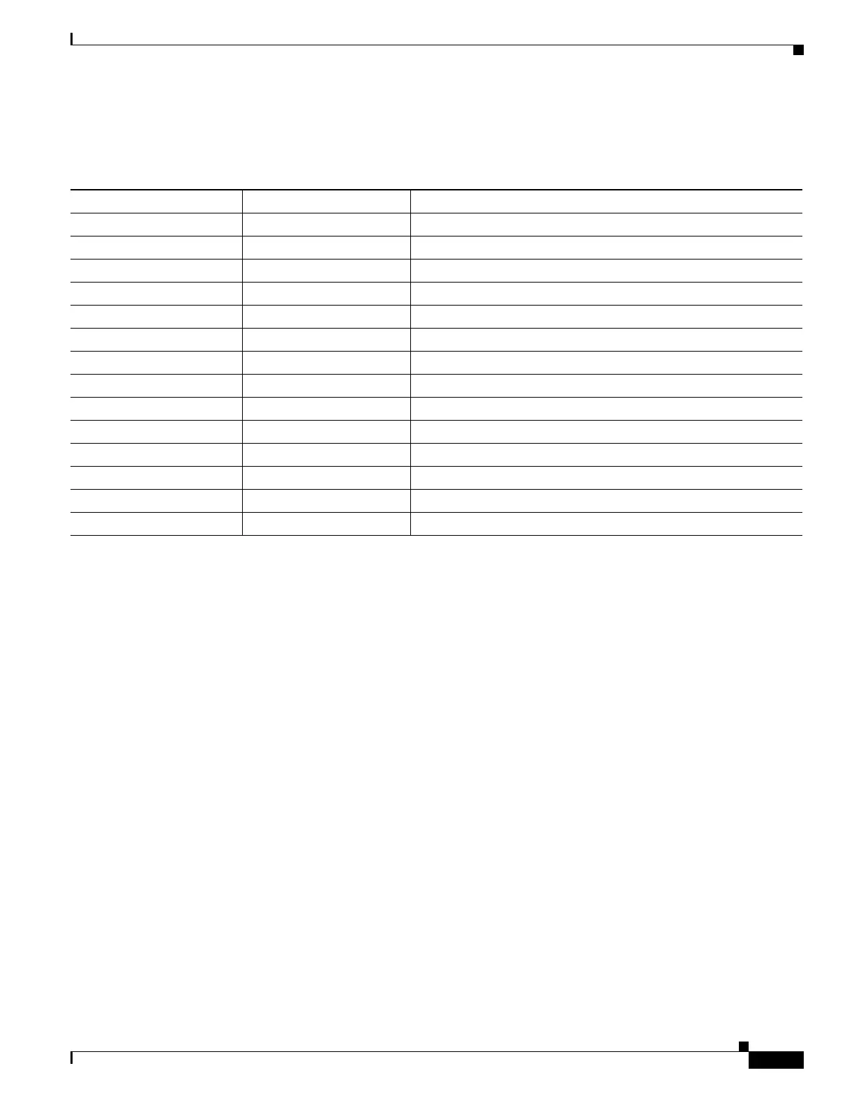
In Table 3-3, read the status and fault LED states together in each row to determine the event that cause
this combination.
Table 3-3 Rear Power Supply LED States
Green PSU Status LED State Amber PSU Fault LED State Event
• Solid on • Off 12V main on (main power mode)
• Blinking • Off 12Vmain off (standby power mode)
• Off • Off No AC power input (all PSUs present)
• Off • On No AC power input (redundant supply active)
• Blinking • Solid on 12V over-voltage protection (OVP)
• Blinking • Solid on 12V under-voltage protection (UVP)
• Blinking • Solid on 12V over-current protection (OCP)
• Blinking • Solid on 12V short-circuit protection (SCP)
• Solid on • Solid on PSU fan fault/Lock (before OTP)
• Blinking • Solid on PSU fan fault/Lock (after OTP)
• Blinking • Solid on Over-temperature protection (OTP)
• Solid on • Blinking OTP warning
• Solid on • Blinking OCP warning
• Blinking • Off 12V main off (CR slave PSU is in sleep mode)