3-46
Cisco UCS C240 M4 Server Installation and Service Guide
OL-32474-01
Chapter 3 Maintaining the Server
Installing or Replacing Server Components
g. Carefully push down on both ends of the PCIe riser to fully engage its circuit board connector with
the socket on the motherboard.
Step 6 Replace the top cover.
Step 7 Replace the server in the rack, replace cables, and then power on the server by pressing the Power button.
Step 8 If you replaced a RAID controller card, continue with Restoring RAID Configuration After Replacing a
RAID Controller, page C-25.
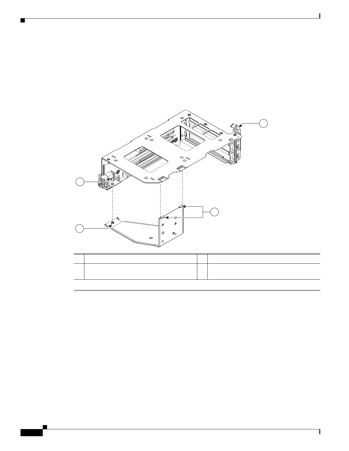
Figure 3-26 PCIe Riser Securing Features (Three-Slot Riser Shown)
1 Securing plate hinge-tabs 3 GPU card power connector
2 Securing plate thumbscrew (knob not visible
on underside of plate)
4 Card-tab retainer in open position